Analog Electronics Basics: Scaling Voltage Rails
Published December 8, 2020
The problem I'm going to be talking about today is how to translate an analog signal from one range to another. I have dealt with this problem three times now, each time was more unintuitive than the last so I thought it'd be useful if I wrote down my process for other people to see what's going on and solve their similar problems.
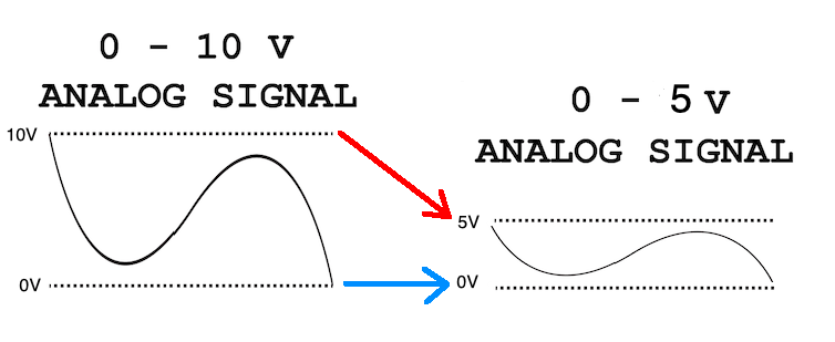
Mapping analog voltages between two rails
An example of this problem
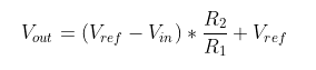
Let's say you're using a complicated device, which takes in some analog/digital signal in order to control some aspect of itself. As an example, let's say it controls its position. You go to measure the device's current position to control what position you actually want it to go to, but discover from the datasheet or your fried microcontroller that the analog signal out from the device has a different rail-to-rail voltage than your microcontroller. It runs at ±15V and your board runs from USB's 0-5V!
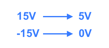
Mapping of voltages that would fix your problems
You grab a new Arduino from the scrap heap and think about how to fix this problem. So clearly, if you could just divide all signals by six and then add 2.5V, the rails would match and you would be able to lock onto the signal from the microcontroller. Voila! Easy as cake. Implement an adder op-amp, then have another op amp with feedback resistors so that it divides itself by 6.
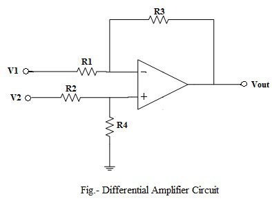
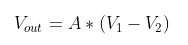
However, you can do it using just one op amp. Introducing, the differential op amp!
Difference op amp, or subtractor op amp schematic
What they don't tell you
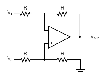
So most of the top Google results that show you how to implement a differential or subtractor op-amp configuration place some limitations on the problem to make it easier to solve. Maybe they say the resistors R1/R3 and R2/R4 have the same ratio, like the first result on Google, the electronics-tutorials site.
Electronics Tutorials subtractor op-amp configuration
Or, they might assume that the signal is zero-centered when telling you the gain. Both the site I cited above and the 2nd result on Google (this site) assume both of these things. But this isn't necessarily what you're looking for. It doesn't matter if their example op amps solve for
, that doesn't move the center voltage at all. And it gets worse if you want uneven gain on either side of the center, which may not be zero. What to do?
How to solve this
Here's the full solution.
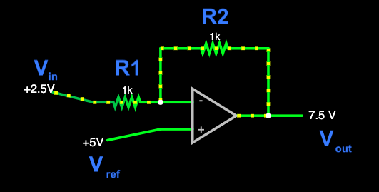
Given this circuit above,
Seems easy, right? It is! And it shouldn't have been so hard for me to figure that out!
How's it work?
So let's go over it. R1 and R2 are feedback for the Vin, they do the dividing of Vin in the circuit. The tricky part is the Vref, and especially how it interacts with the Vin. It gets subtracted, sure, but if Vref is not zero then it's going to show up in your final output as well.
You may be saying "Ohh, but Andy, this isn't like a differential op-amp at all! The noninverting input doesn't even have resistors." Well to that I say, how do you expect to make your reference voltage? You'll usually have to make a voltage divider to ground, and voila, the original subtractor structure appears.
Example please?
Sure! Let's say we're solving the above mapping: from ±15V rails to a 0-5V range. This op-amp is in an inverting configuration (negative feedback), so the higher initial voltage is going to have to map to the lower voltage on the output, and vice versa. Here's what we're trying to accomplish.
Mapping of voltages that would fix your problems, pt. 2
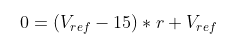
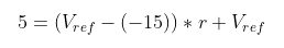
We can just plug in our knowns and solve the linear system of equations for Vref and the resistor ratio. Let's say R2/R1 = r just so we can write it more easily. From the first equation, we have Vin = 15V, Vout = 0V, and the second equation we have Vin = -15V and Vout = 5V. So in LaTeX form:
Then we just ask Wolfram Alpha! I'm using v for Vref to make it easier to type.
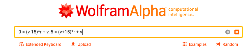
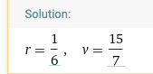
Great! So our R1 has to equal 6*R2, and our reference voltage should be somewhere around 2.14V.
Implementing the resistor ratio and voltage divider
I want to pick realistic resistors because these circuits are usually needed immediately and in real-life, so I usually use a resistor ratio calculator to make this easier. This site is a godsend. I'm really lazy in real life, so I'm only going to use the single resistor in series option, but the other ones are usually a little or a lot better in terms of error.
For the resistors with a ratio of 1/6, it seems a good choice is a 56kΩ and 330kΩ resistor.
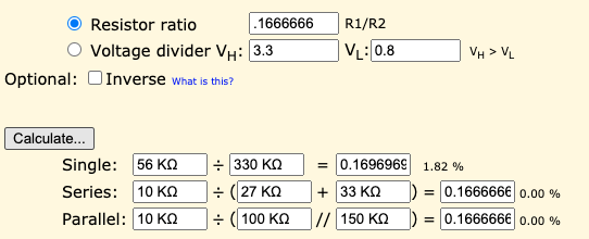
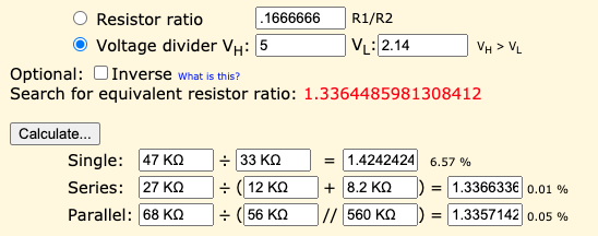
We'll assume we have access to a 5V source since the second set of rails is 0-5V. We can use the handy voltage divider option on the site to solve for this ratio all at once. Looks like a 33kΩ and 47kΩ resistor will do the trick.
Does it work?
Here's the part values we picked out in simulation:
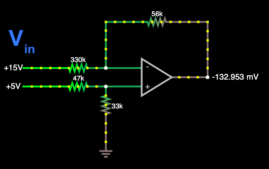
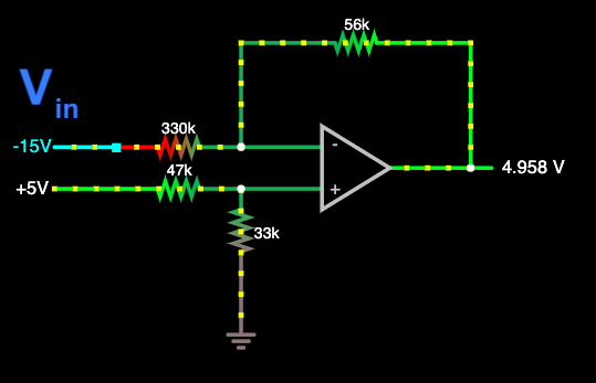
The +15V rail becomes -0.13V, so very close to the 0V we wanted it to be. The -15V rail nails 5V almost exactly. So yea, I'd say they work.
Sometimes the solution with realistic resistors will need some tuning, because negative voltages will usually damage a circuit, but you can just tune the initial parameters on the initial voltage mapping to be a little tighter and solve the problem again.
Closing
Anyway, I encounter this problem all the time, and as I work more with hardware I think this is an integral "glue" circuit that you should master if you're going to work with hardware of various logical and analog levels. That's all for now, cya next time!