Programming an ATtiny85V using an Arduino
Published February 2, 2024
Hello! Today I'm gonna walk you through uploading code to an ATtiny using an Arduino. This was my first time programming a microcontroller off-board, and I got most of the process following this video. But that video was not sufficient alone, so I'll be describing some of the extra steps in this post.
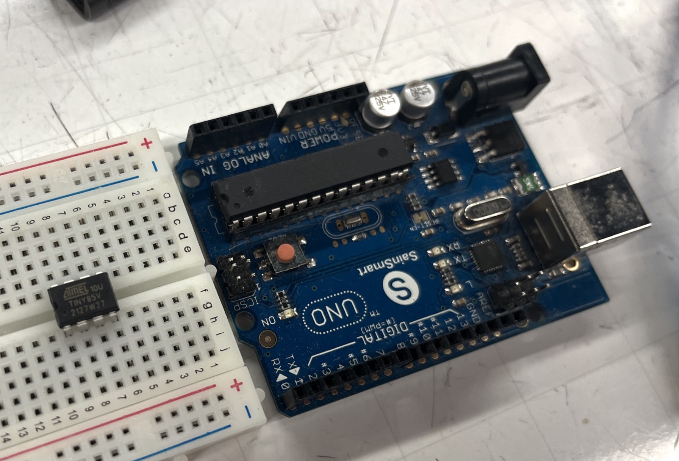
Ingredients
You'll need an ATtiny25/45/85 chip, Arduino, 6 jumper wires, a resistor + LED, and maybe a 10uF capacitor.
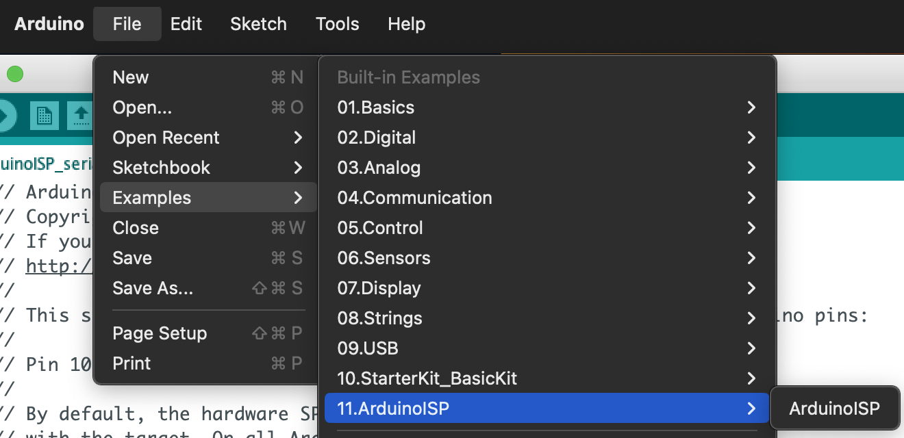
Prepping the Arduino
First we must flash the Arduino with the ArduinoISP sketch (found in File->Examples->11.ArduinoISP). We are using the "old style" wiring, so also uncomment line 81 in this sketch.
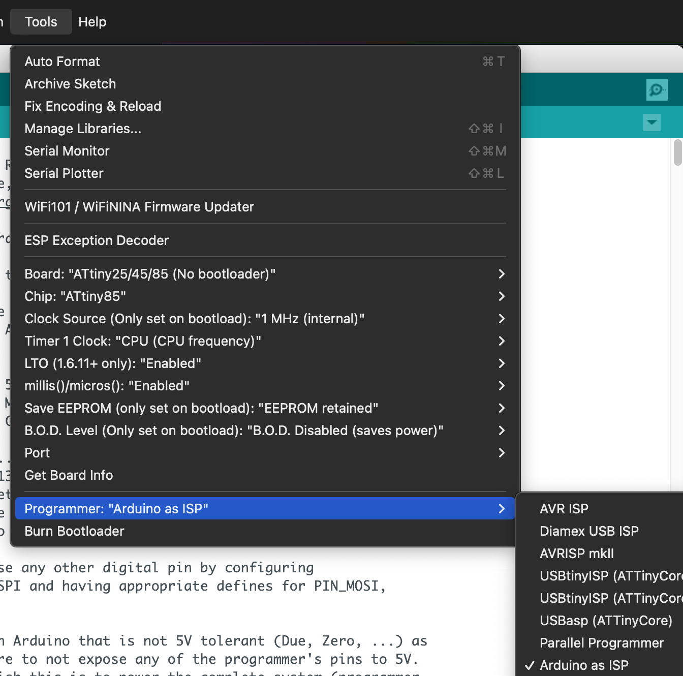
We're not going to program the Arduino again, so go ahead and switch the target board to "ATtiny25/45/85" in Tools. If you don't have this option in your boards, follow the instructions in the ATtiny repo.
Change the programmer to "Arduino as ISP" as in the image below, and we'll be ready to go.
Wiring the ATtiny
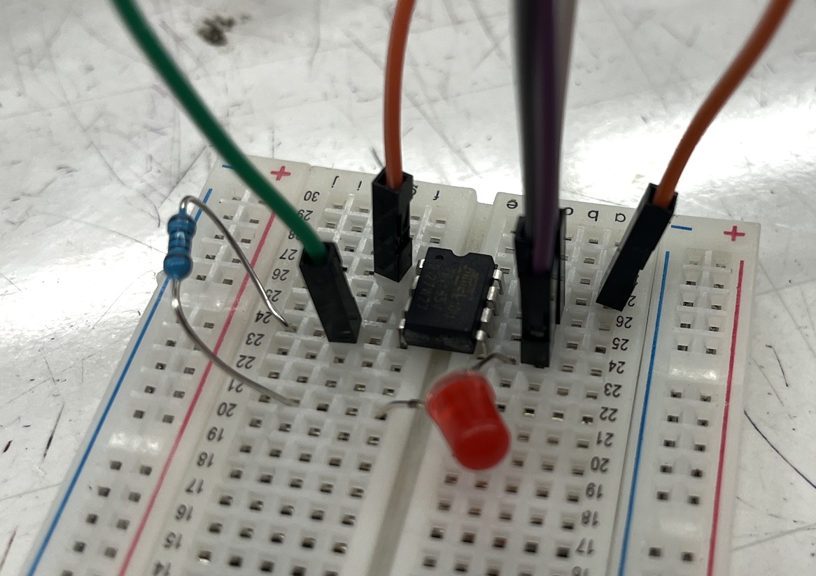
Now we're going to need those jumpers. Follow this wiring diagram from the video above so we can upload code to the ATtiny
[source](https://www.youtube.com/watch?v=TUlzOD9T3nI)
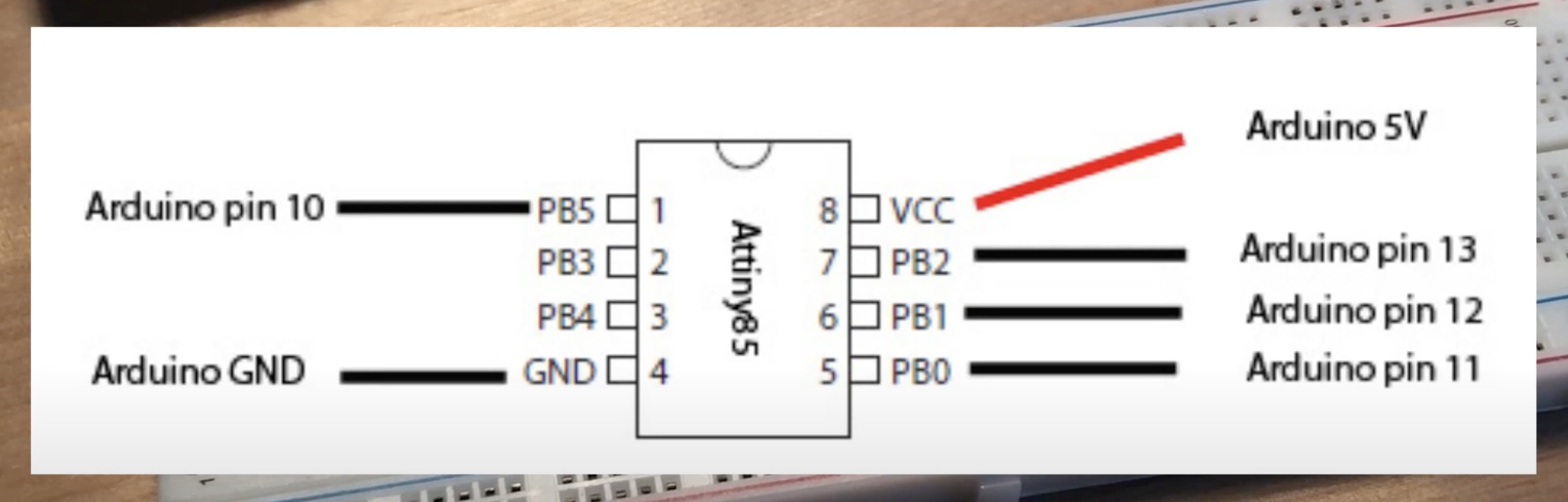
To do the Blink sketch properly, we need to add the LED and resistor across PB0 and GND. Make sure the longer (positive) leg of the LED is on PB0.
Uploading Blink
If this is the first time your ATtiny is being used or you've changed any build settings, you'll need to hit Tools->Burn Bootloader. This should work with no errors, but if you get one, make sure you've uncommented that "old style wiring" line in ArduinoISP and that your wire connections are solid.
Now, open the Blink example sketch. Change all instances of LED_BUILTIN to 0, then upload the sketch. If you have no errors, fortune smiles upon thee. Proceed to the next section.
If you instead get an error like avrdude: stk500_paged_write(): (a) protocol error, expect=0x14, resp=0x10, you'll need to place a >10uF capacitor across the RESET and GND pins of the Arduino to temporarily disable the RESET button. Put it in and hit upload again, and your ATtiny should start to blink. Woohoo!
Uploading SoftwareSerial
To test any non-visual functionality, we're going to want to print debug messages over Serial. While we can't do Serial in the ATtiny hardware, we can include the SoftwareSerial library and do it anyway. The following code is derived from an example on this guide, but you can use the sketch in Examples->SoftwareSerial also.
SoftwareSerial example works, though the pin numbers are all new to me
Sus method
If the ATtiny uses SoftwareSerial, you can route the TX physical pin to the Arduino's TX pin and open the Serial monitor. You should see random noise characters, but if you hold down the RESET button, you can get messages from the ATtiny to show up.
Fine for words, but holding down the RESET messed with my ADC values.
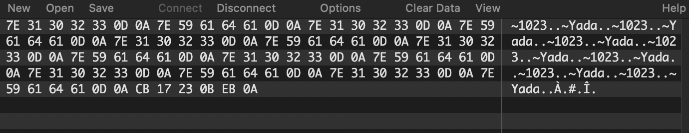
The ATtiny's messages are scrambled when we receive them over Serial because the Arduino also uses the RX/TX pins and they're physically routed to the UART->USB converter chip. By holding down the RESET, we disable the Arduino and get to see the ATtiny messages without any problems.
Less sus method
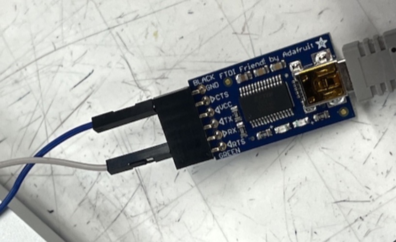
The proper way is to get an FTDI Friend or other UART->USB converter and receive messages using that instead.

If you go this route, the ATtiny's TX goes into the FTDI Friend's RX, and the GNDs are connected. The port will have to be changed, and the messages will be received just fine.
Trying out the ADC
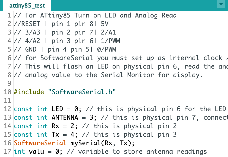
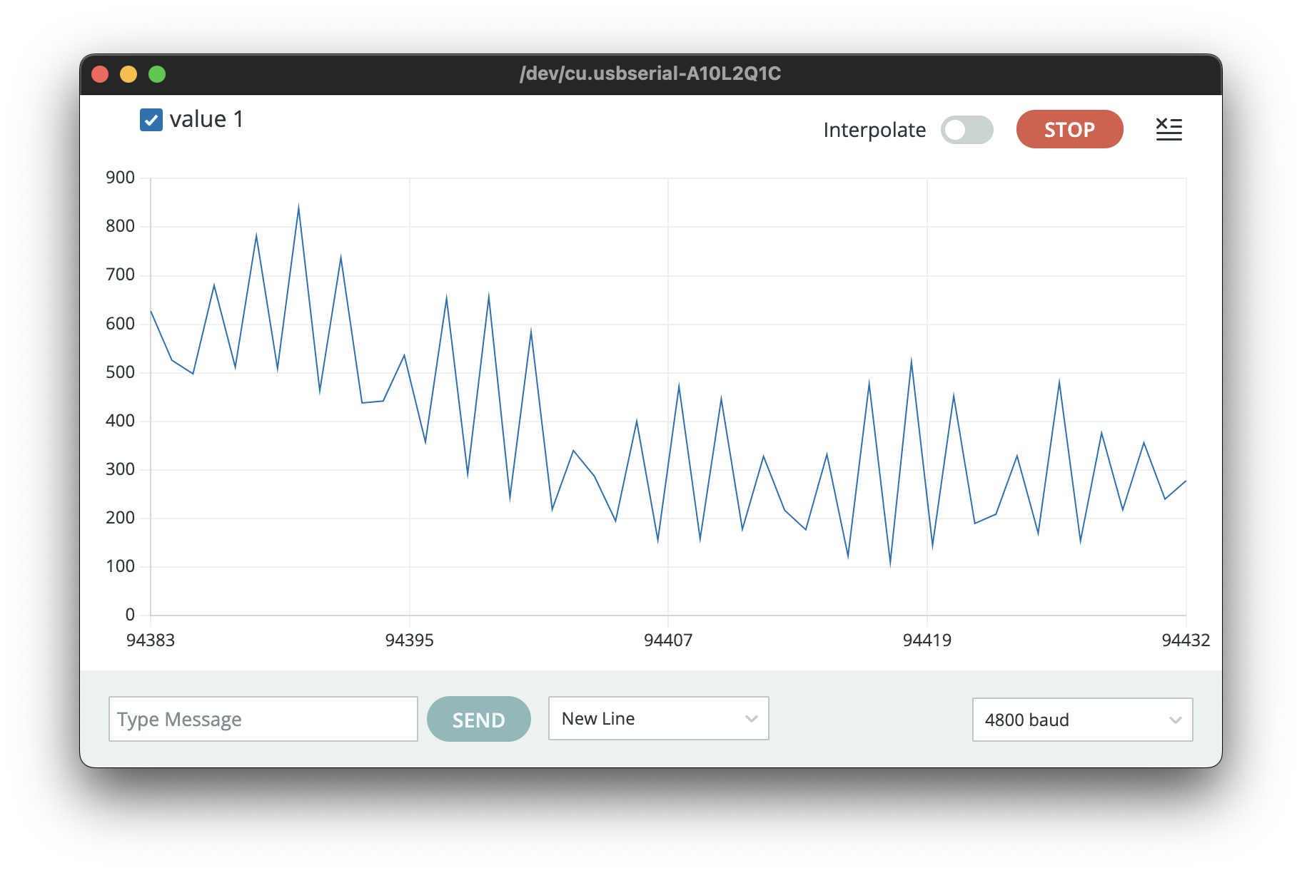
The ATtiny85 is big enough to fit a lot of the Arduino helper functions, so the analogRead function just works like normal. You will need to be careful to pick a pin which can receive analog, so be sure to check. Here's my code to read from pin 2 and print it to Serial.
#include "SoftwareSerial.h"
const int LED = 0;
const int ANTENNA = 3;
const int Rx = 2;
const int Tx = 4;
SoftwareSerial mySerial(Rx, Tx);
int valu = 0; // variable to store antenna readings

void setup(){
    pinMode(LED, OUTPUT); // tell Arduino LED is an output
    pinMode(ANTENNA, INPUT);
    pinMode(Rx, INPUT);
    pinMode(Tx, OUTPUT);
    mySerial.begin(4800); // send serial data at 9600 bits/sec
}

void loop() {
    valu = analogRead(ANTENNA); // read the ANTENNA
    mySerial.println(valu); // send the value to Serial Monitor, ^Cmd-M
    digitalWrite(LED, HIGH); // turn LED ON
    delay(10); digitalWrite(LED, LOW); // turn off
}
ADC readings plotted over time
Have fun!
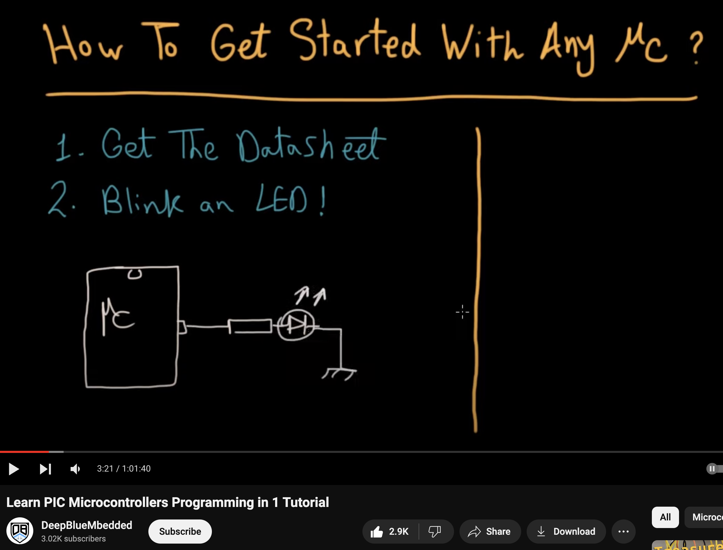
Hopefully you know the basics. As DeepBlueMbedded said, you're basically done once you get blinking.