A computer scientist's guide to I2C
Published February 5, 2024
Hello! I am continuing on my last post, this time we're making an ATtiny do I2C.
As a CS person, I didn't really need to learn how to do I2C since every chip I've used before came on a breakout board and had a nice GitHub library I could steal. Eventually I needed to learn it myself to use cooler chips, and the post you're reading now is the post I wish I had when I started learning how I2C works.
This post from the Cave Pearl Project initially helped me understand I2C, but it assumes a bit more knowledge than this one.
I2C is like an API for ICs
If you've ever worked with big Python libraries with unwieldy documentation and a million functions, it may help you to think of I2C as a similarly big library for hardware. Specifically, I'm thinking of matplotlib. You read and write options using matplotlib functions, you pass data, magical stuff happens internally, and voila, graph! And if it breaks, debugging is confusing because the functionality that breaks is usually buried deep in the library.

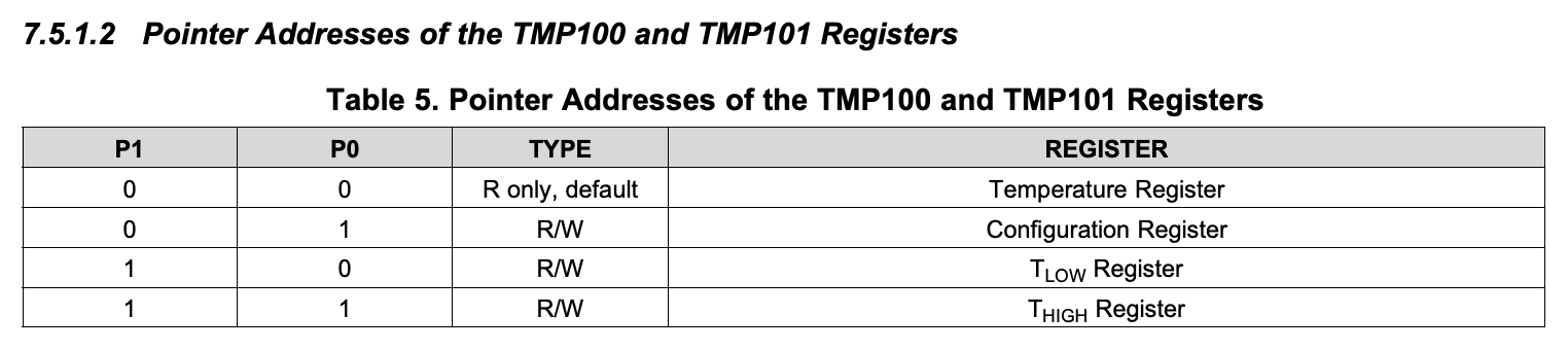
I2C has similar functionality, except instead of calling a nice English function like plt.clear(), you need to say "write 0x1 to the SHUTDOWN register at position 0x10". Chips using I2C have a bunch of data and config registers. To access a sensor reading, you say "let me have 8 bytes from register XX". To configure sensor settings, you say "write XX into register YY". This makes it a bit more annoying since register addresses are harder to memorize than function names in English. You will usually be checking the datasheet a lot.
Normally you need to instruct the microcontroller to bit-shift your message out as bytes, but the Arduino Wire.h library makes this easier by providing functions like Wire.write(0xFE).
Example table of the register locations from an I2C sensor datasheet
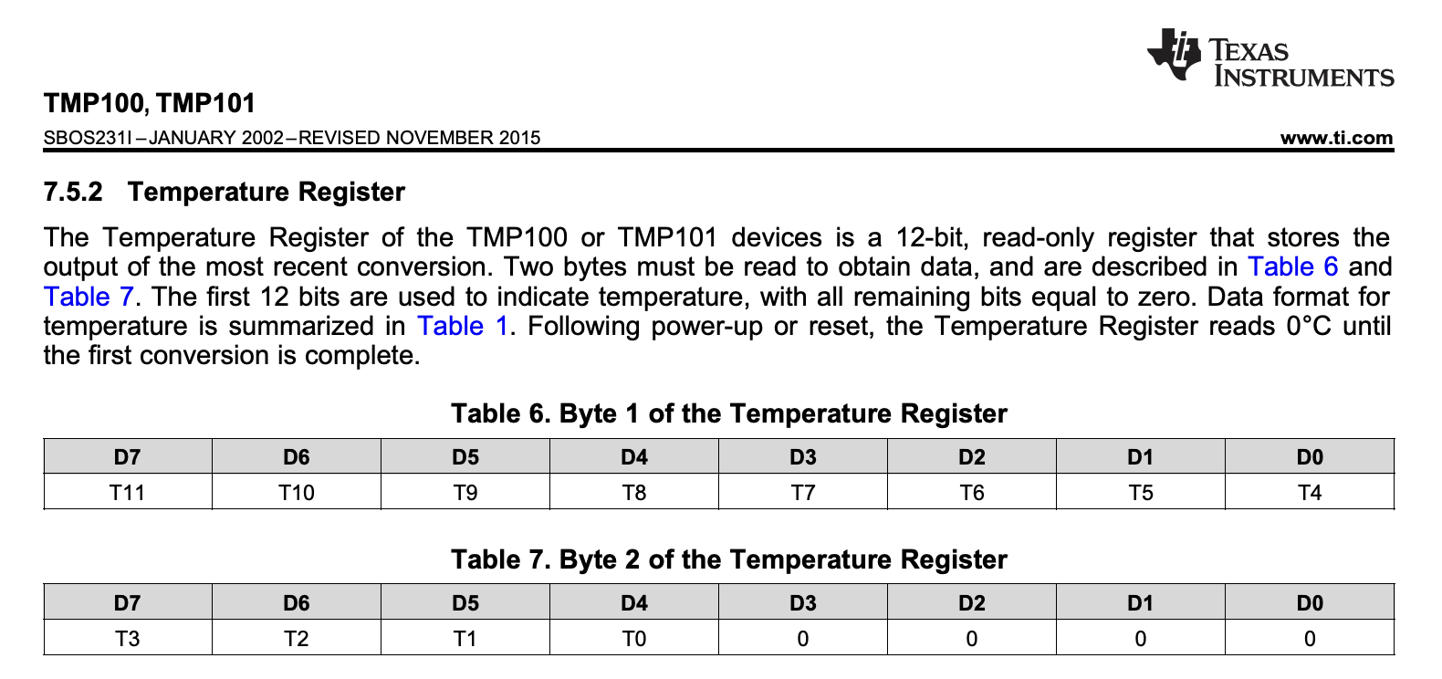
Example table describing what the bytes mean in a particular register
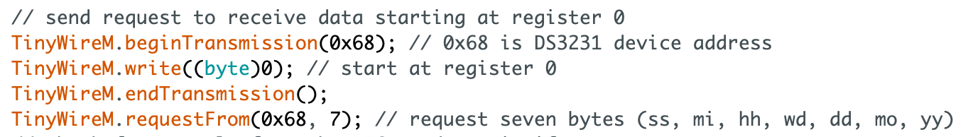
Also unlike software, hardware functions cannot be called willy-nilly. Since multiple I2C chips can share the data line, each chip expects the I2C master to say "Hey, I'm gonna write to device address 0x43" or "Hey, I'm gonna read from device address 0x44" before reading or writing. The reads and writes are called "transmissions", so these start and stop messages are called beginTransmission and endTransmission.
An example I2C transmission which tells the sensor which register to send data from
Since each I2C chip comes with a pre-programmed address, if two of the same device share a data line, you will not be able to communicate with them separately. This is why I2C chips usually come with a shutdown pin, so the main microcontroller can turn off all except one to say "Device 0x43, you are now called device 0x45" to talk to them separately when they're all turned on.
Ok, get on with the example!
Most popular I2C chips come on a breakout board, and this usually guarantees the existence of at least one GitHub library that makes talking to the sensor easier. These libraries turn "hey device 0x43, read 8 bytes from register 0x42, end transaction" into a handy function like readSensor(). But sometimes, they don't have it. Other times, you want to learn how it works.
Pic from the last post
I recently got an ATtiny working on a breadboard using an Arduino Uno as the programmer. Afterwards, I also wanted to use an I2C RTC chip (real-time clock) with the ATtiny — while there are I2C libraries for it, they are written for the Arduino. And since the ATtiny25/45/85 doesn't have hardware I2C support, the Wire.h library that eases I2C transactions doesn't work, so the RTC libraries need a bit of editing. The ATtiny uses the TinyWireM.h library instead as a (basically) drop-in replacement, you should be able to just replace all Wire with TinyWireM.
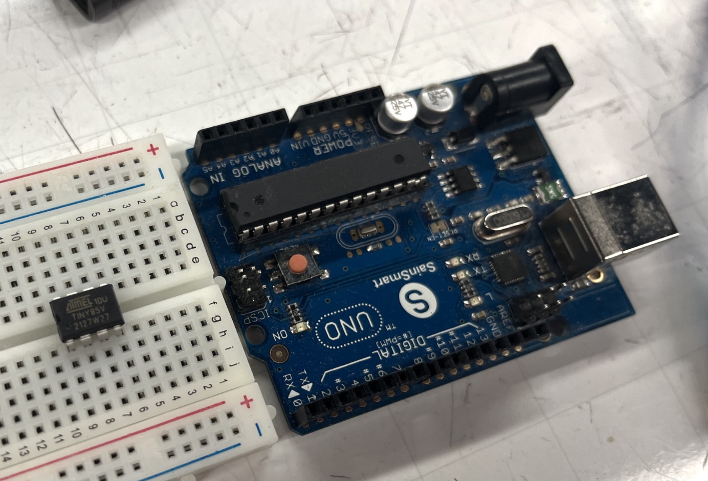
I really wanted to manually understand the I2C stuff, so I found a DS3231 (aka ZS-042) minimal example on the Arduino forums and converted it to use TinyWireM. On the ATtiny, the I2C pins are SDA on physical pin 5 and SCL on physical pin 7 (these are also known as PB0 and PB2 respectively).
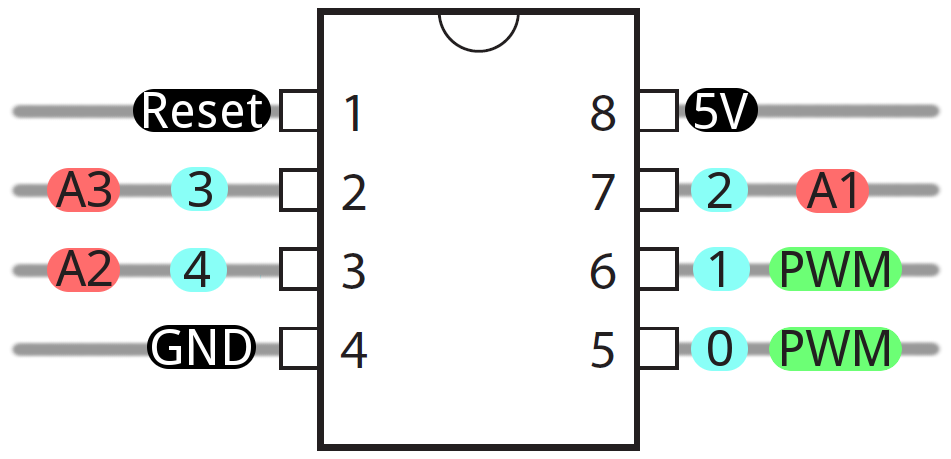
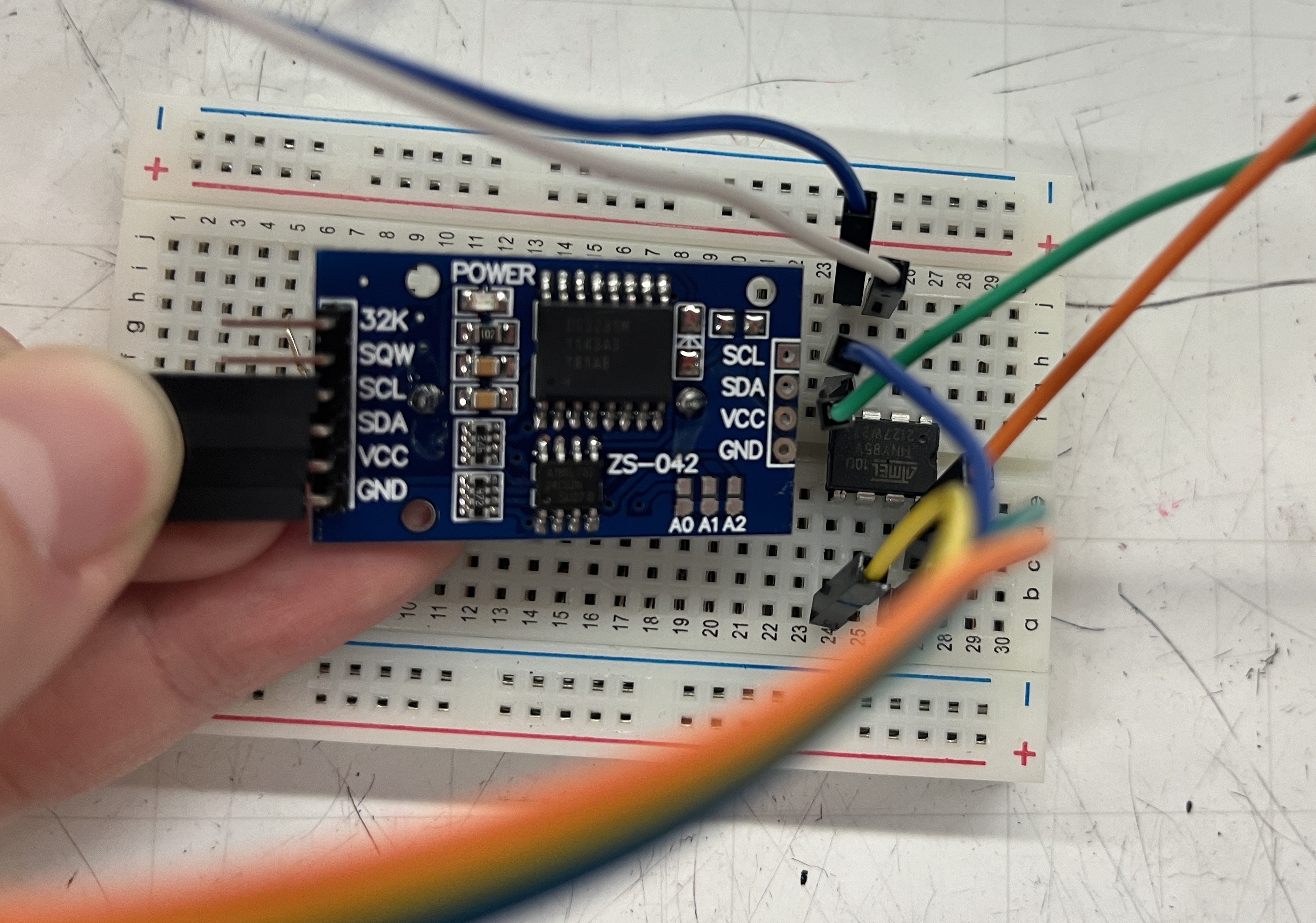
I've added SoftwareSerial so we can receive the ATtiny messages using an FTDI Friend, its RX should go into physical pin 3 (same as my previous post). Wires from the ZS-042 board are SCL -> pin 7 and SDA -> pin 5. V+ and GND also need to be connected.
Wiring
Here is the ATtiny code. It's simple enough to read and understand, and you can compare it to the datasheet to understand what registers are being written to and what the intended purpose is.
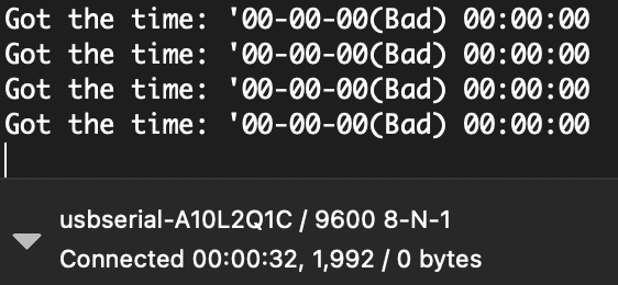
I'm using the Arduino to flash the ATtiny. After flashing, I had to unplug the programming wires from the ATtiny's physical pins 5, 6, 7 or else they interfere with the SDA/SCL messages from the RTC and you get a message like "Time=00:00:00(bad)".
What your serial monitor should NOT look like
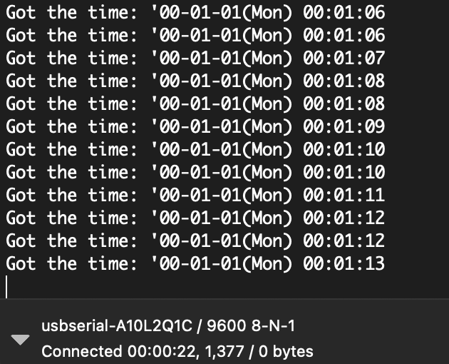
Here's what the Serial monitor should look like when it's working properly:
Yay, free time
Conclusion
It is annoying and tedious to read the 50-page datasheet and translate all the register addresses and values into functions that can be used for your application, but it is the only way. I got into I2C hoping there was an easier way to convert the datasheet into usable functions, but much like using matplotlib, the easiest way is through. At least we can be thankful for the Wire.h and TinyWireM.h authors who have written the even lower-level functions for us.
Cya next time!