Body Channel Communication Tutorial Pt. 1
Published April 17, 2021
Hello! Today I'm going to be talking about some preliminary experiments I did involving body channel communication, or BCC. BCC is a technique that uses the body's natural conductivity as a signal path, allowing your devices to talk to anything you touch. I implemented a basic version that requires a shared ground, some experiments from an implementation without a shared ground, and show practical techniques that worked for me.
Transmitting signal over the skin
Background
Why would you want this?
Despite your body's high resistance, large voltage changes propogate fairly well across it. If you wear a watch or some other device, it can digitally write out an I2C/UART/bitwise ASCII signal to a pin that's touching your skin by bringing the pin high and low. This digital logic signal propagates through you to whatever you're touching.
If the device sends out your student ID, anything device you touch can now identify who is touching it. If it sends out your credit card information, you can pay with just a touch when checking out.
Best of all, it works the other way. If a device is writing bits out to a surface, your watch can also detect when you touch something. If each device transmitted its own MAC address, your watch would know what you touched, and would be able to talk back to it through you.
But doesn't sending a signal require two wires for ground and signal?
Very astute! It does! However, because the body is so conductive, it naturally couples capacitively to the environment around it. This means that the device and the human can share a ground connection without an additional wire; the device is grounded through the building's wiring, and the human through their salty body.
The downside to this is that the ground connection is rather weak. The human-ground capacitor is estimated to be about 100pF or less, so signals don't cross the human-device THAT well. However, there has been research exporing how to robustly use BCC even with this weak connection. More details can be found in [1] and [2].
What I did
Hardware
My setup is very simple. I used two Arduinos, two 180kΩ resistors, and two jumper wires. There is a "sender" Arduino imitating a smartwatch, and a receiver Arduino imitating a payment terminal or another interactive device.
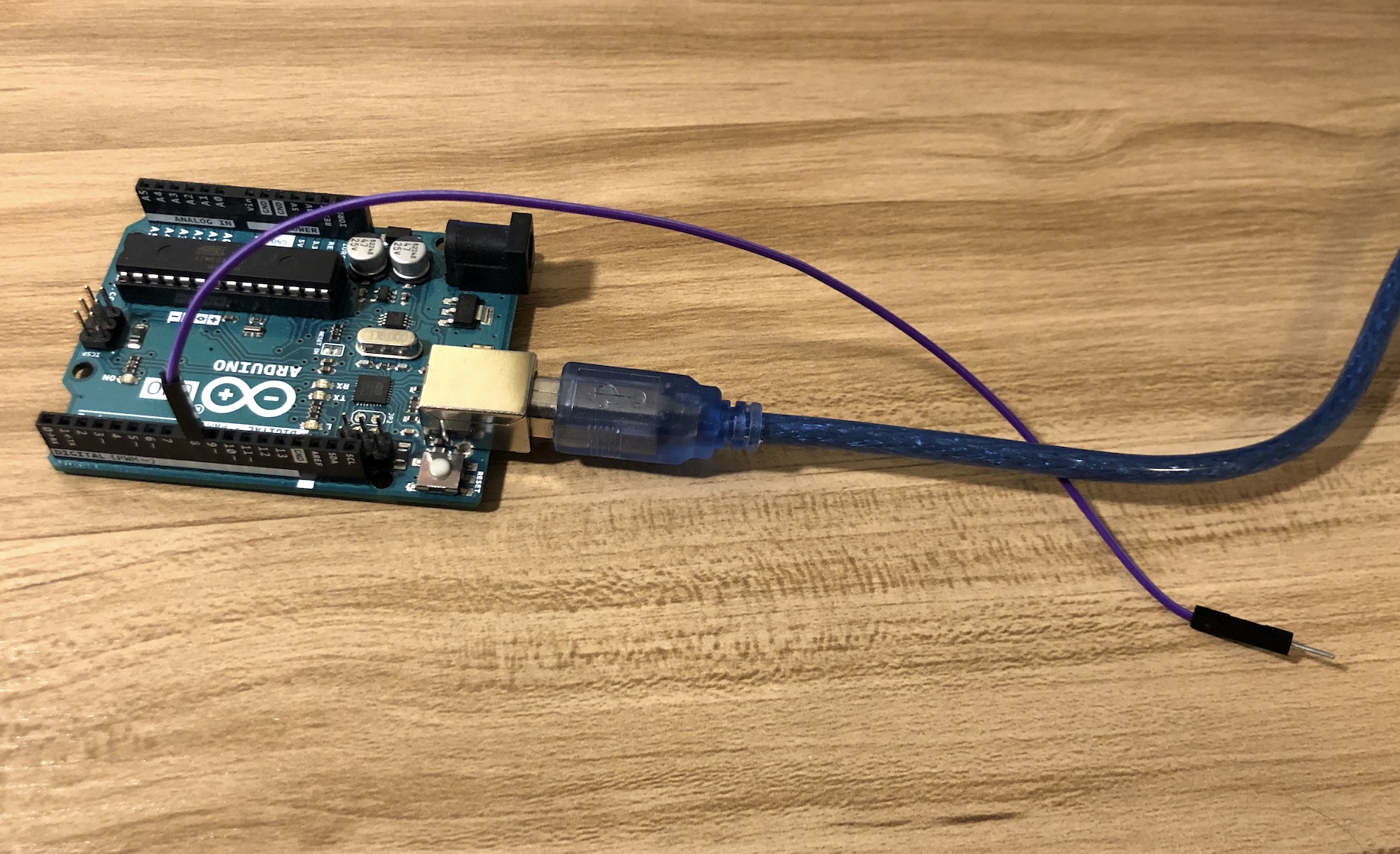
The sender has just a single jumper out, and it's digital writing a 10Hz square wave to the jumper wire.
Sender Arduino
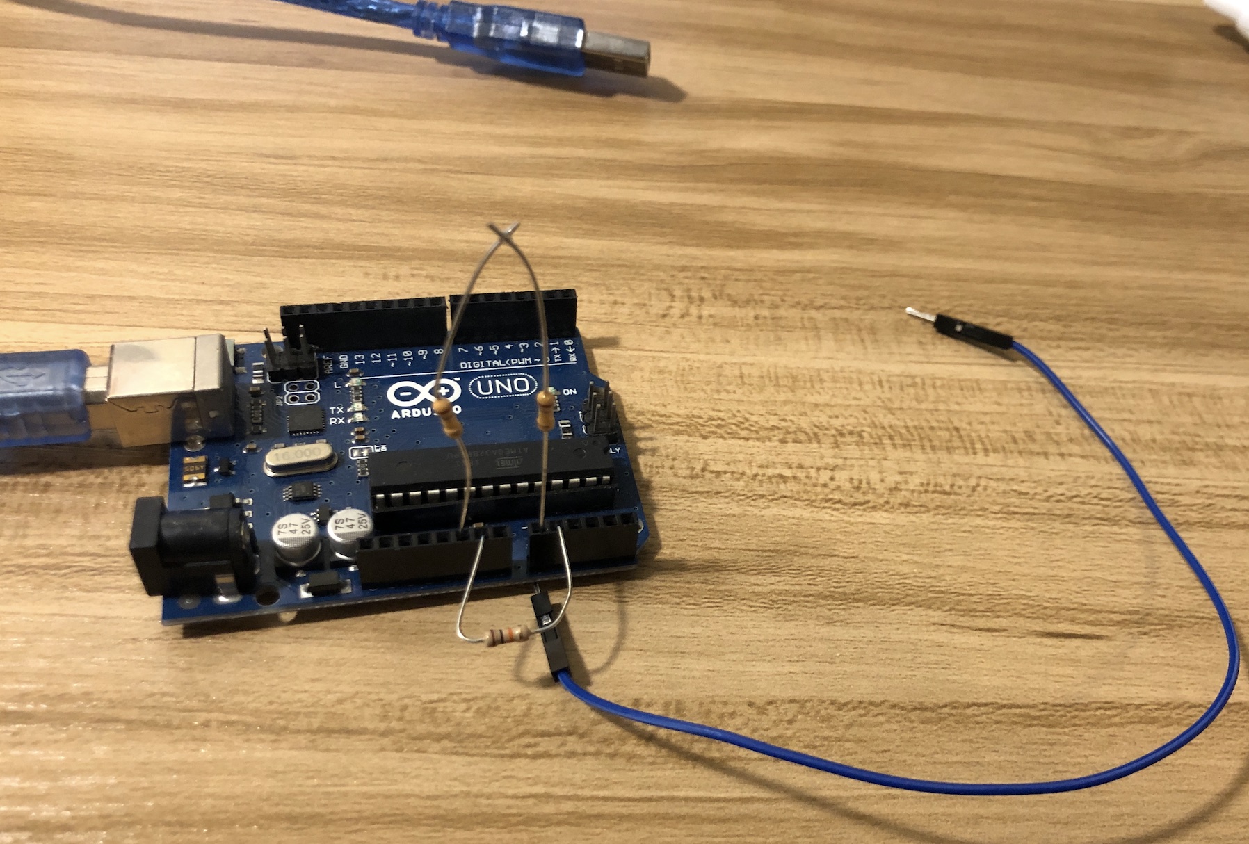
The receiver has a jumper wire on analog pin 0 which is reading at 100Hz. A 360kΩ resistor connects that pin to the ground pin. The extra resistor at the bottom is for measuring a ground truth analog reading, which I'll talk about later.
Receiver Arduino
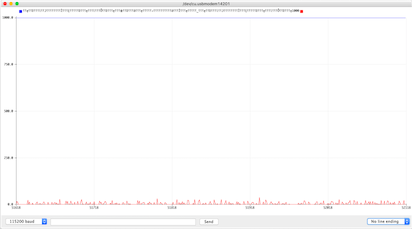
The resistor is necessary because of the EMI pickup when I added the jumper wire to the analog pin. Here's the noise on the analog pin, then with the jumper, then when I hold the jumper with my finger.
Baseline analog pin readings
Analog pin readings with jumper wire attached
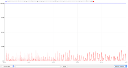
Analog pin readings with human holding jumper wire
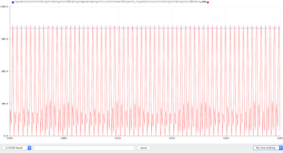
The human body acts as an antenna for 60Hz noise, and my body is no different. The spikes you see in the last image are from my environment, and would destroy our signal without the resistor to ground. The smaller the resistor, the easier the environment's noise gets leaked away from the pin. However, this easier leakage also reduces our overall signal more, so I picked a large resistor that approximately matched my skin's resistance.
Signal (Shared Ground)
Shared ground BCC setup (technically they're already connected through the laptop's ground)
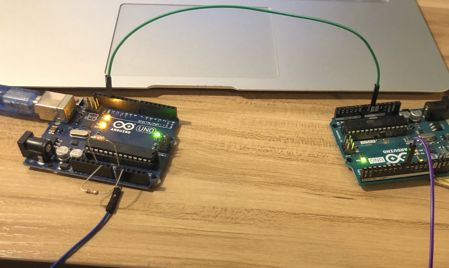
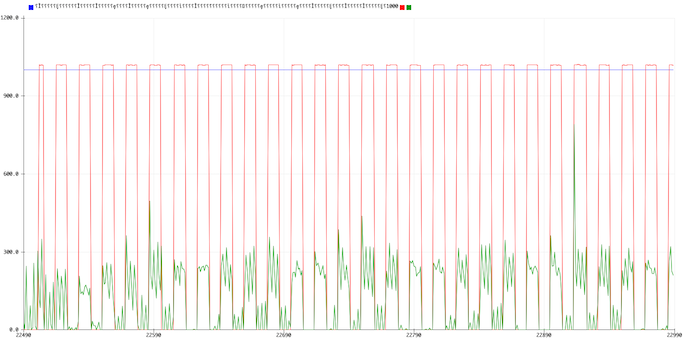
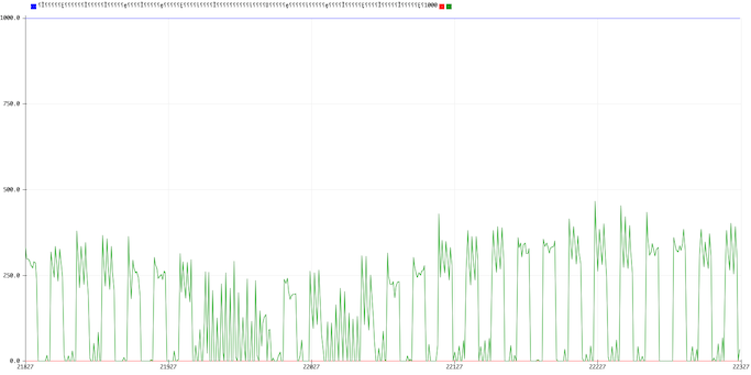
To transfer the signal, I touched the output jumper of the sending Arduino, then touched the input jumper of the receiving Arduino. I also pressed the output jumper directly against my other input, to capture a reference for what the output pin's signal looks like directly.
Square wave being transferred over human touch. Green is the pin I'm touching, red is the reference pin

The signal transfer is pretty clear. The green line is what the receiver reads from my finger, and the red is the actual output of the pin. There's a bit of interference from the ADC, but even without the reference pin the signal transfers really cleanly.
Square wave being transferred over human touch sans reference
Here's what the noise looks like in the setup if I hold the receiving pin without touching the signal pin.
Noise when touching receiver pin without touching signal pin
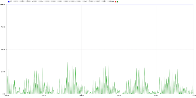
The no-touch signal is a bit noisier than I would like, but definitely different enough from the touching signal that we would be able to detect it.
Signal (No Shared Ground)
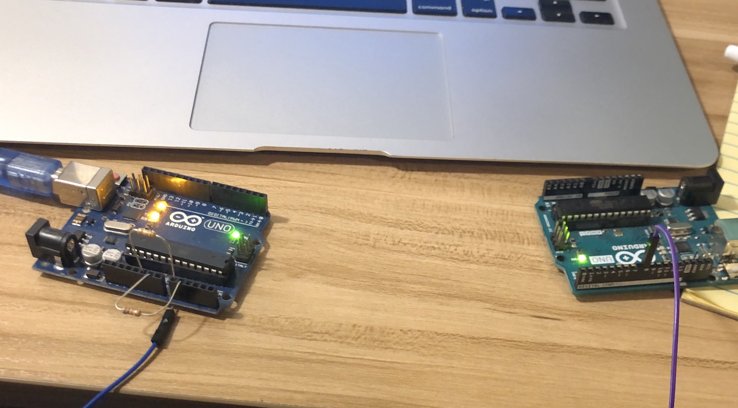
I connected the sending Arduino to another computer when I did this experiment. The receiver is plugged into my laptop, which was not connected to the wall outlet at the time.
No shared ground BCC setup
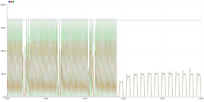
Without the shared ground of my laptop, the problem gets a lot harder. I first tried holding the signal and receiving wires to compare the shared vs unshared grounds. The square wave is lost in big noise of a completely different frequency, and comes straight back when I connect the grounds again.
Unconnected vs. connected ground BCC signal
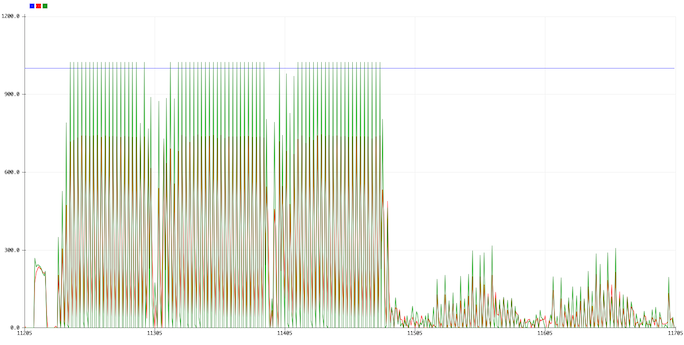
I was worried that the signal wasn't actually getting through at all, but it does. I tried holding the signal wire, then dropping it but still touching the receiving wire.
Received signal while I hold the signal wire then release it
And when I hold the receiving wire, then drop it, the signal goes to our nice analog baseline.
Received signal while I hold the receiving wire then release it
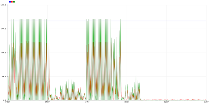
The detection is sizing up to be fairly tricky, but I think that we should be able to detect the signal even when the grounds are not shared. There's already a clear difference between touching signal and not, but we need to do some work on conditioning the signal to better cross the human-pin divide.
Next steps
This is a 10Hz signal, which is fairly slow. We can make it much higher, but I needed to go low to show the plots properly on the serial plotter. However, we're limited by the ADC time, which is middling on an Arduino. We may need to switch to another microcontroller if we want more speed. With a higher frequency, we also get better coupling to ground, which hopefully gives us a better transferred signal.
We're gonna try bits next! Cya then!