Body Channel Communication Tutorial Pt. 2
Published April 27, 2021
Continuing from last time, I'm trying to make our body channel communication system work without requiring a shared ground between the two devices. And I got it working in a very bootstrapped way, which may be usable for our class demo. Read on for more!
Recap
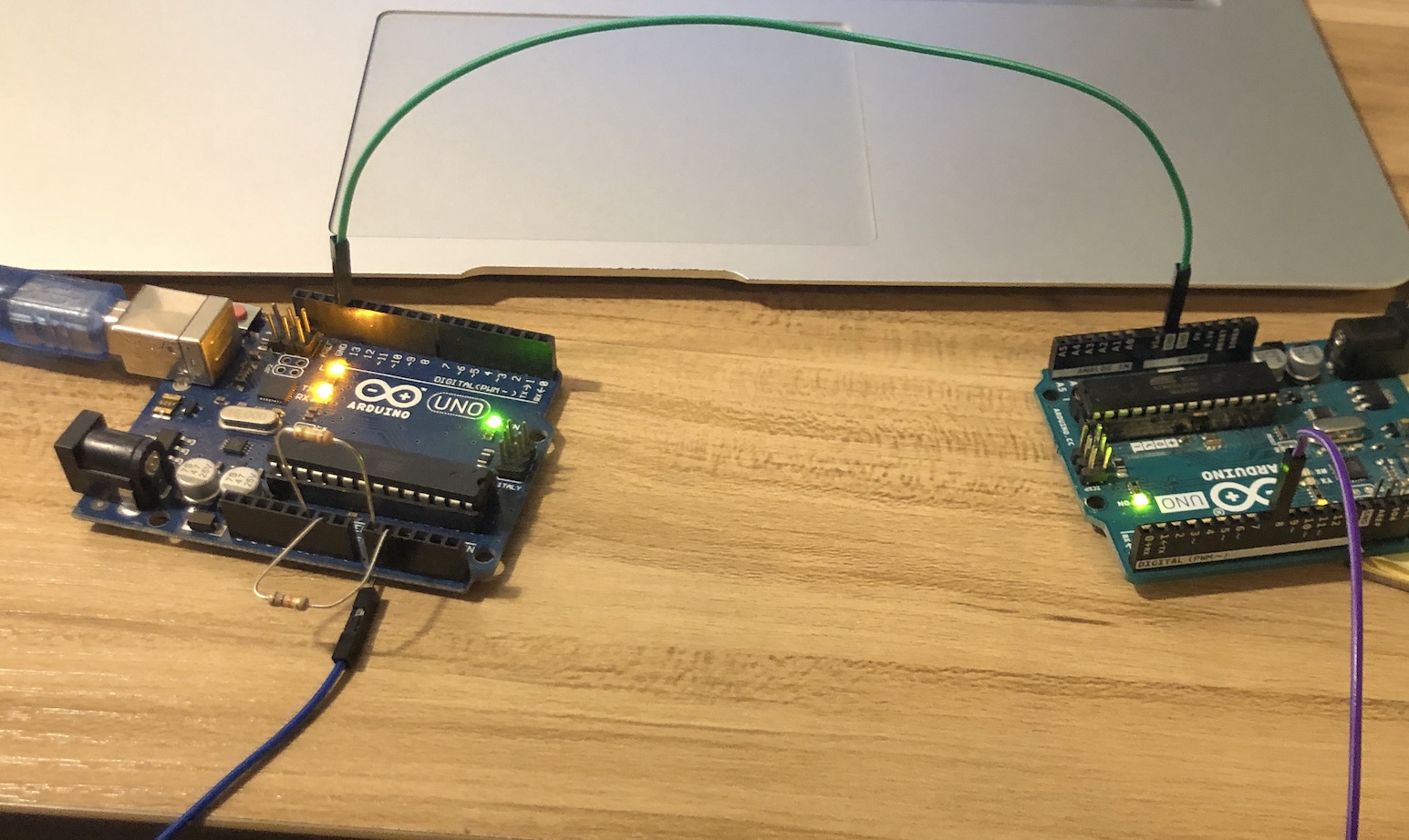
You may remember my two-Arduino setup from last time, using one as a transmitter and the other as a receiver. Ideally you'd want either uC to work for both functions, but that's easily tackled later. The previous setup utilized the shared ground of my computer's chassis to transmit signal reliably. I also showed some experiments I tried without shared ground, and they didn't work as well. The signals sent without shared ground had a lot of 60Hz noise, and the added signal square wave signal swamped the ADC's input range.
Shared ground BCC setup from last post
Propagating higher frequency signals without a ground
Since it's impossible to transmit a voltage with one wire (a potential difference inherently relies on having two "wires"), I decided to fake a radio transmitter. Because the capacitance of the body has decreased impedance for higher frequencies, signals can couple through the body better at higher frequencies. Last time, I used frequencies under 1kHz because I wanted to be able to see it on the serial plotter. No longer!
I wanted to change the transmitter frequency to something closer to 1MhZ. I started with delayMicroseconds(1) between direct digial port manipulation to switch the pin on and off, but got a longer delay than I expected when I measured it on an oscilloscope. Then I switched to using 8 No-ops between the digital switching, and got a faster square wave coming out. A half second timer turned the square wave on and off. The receiver code had no change, I left it analog sampling as fast as it could go.
Side note, I also tried writing the Arduino's 16MHz clock out to the transmitter pin since it's faster. It didn't work. When sending spikes with the clock, the analog readings on the receiver integrated together to a constant voltage, but with a large delay and rise time. Not fast enough!
Picking up the spikes
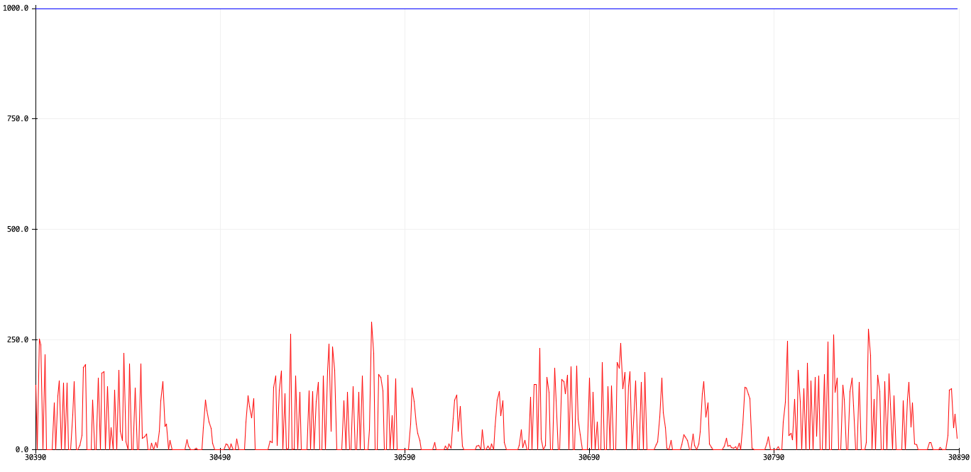
When I first started testing, I realized that there was a great asymmetry depending on what powered the board. I used a USB isolator to "separate" the grounds, and initially I had the transmitter plugged into the isolated USB port. The signals I got had awful 60Hz noise, but when the train of square waves was transmitted you could still clearly see it. If I had stopped here, I would have to deal with a mediocre bitrate and a terrible filtering problem.
The little solid spikes are 60Hz noise, and the denser, thin spikes are periods of transmission.
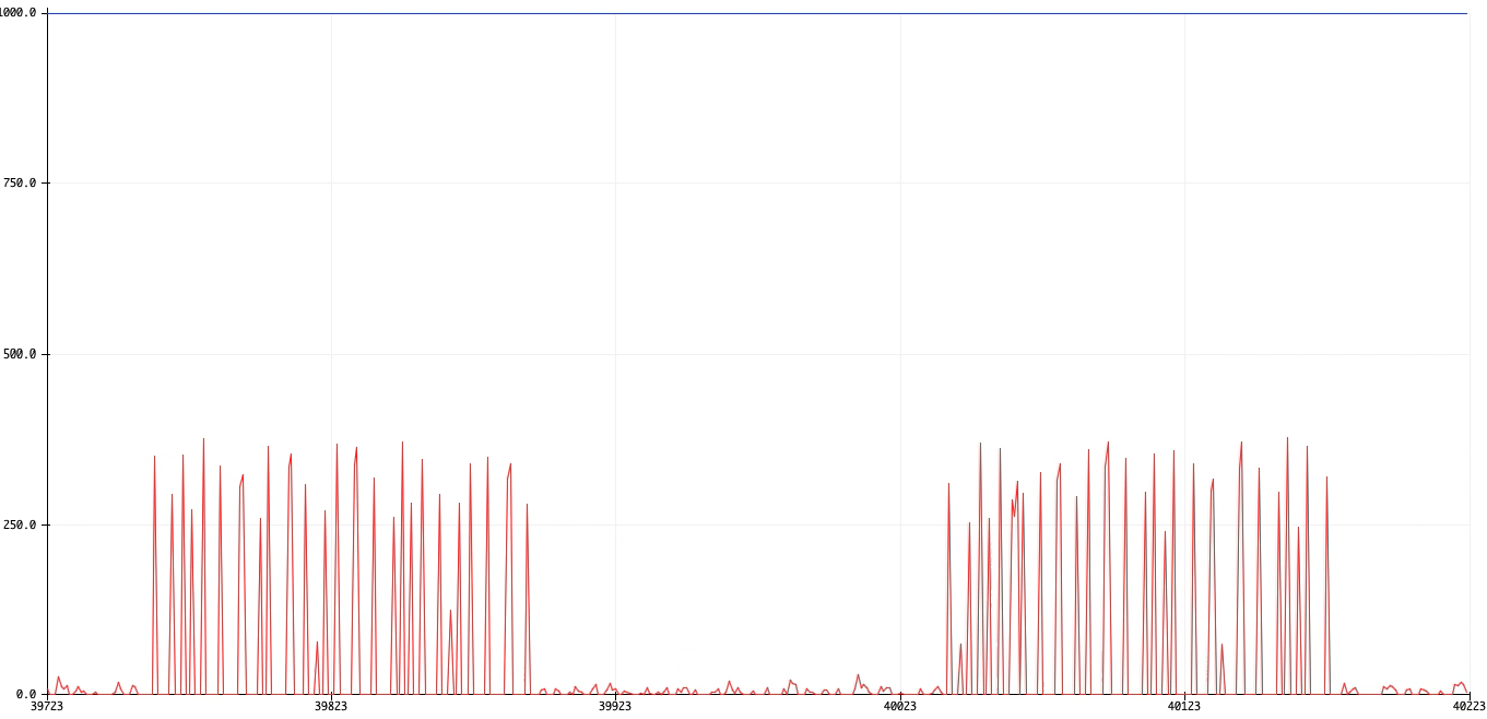
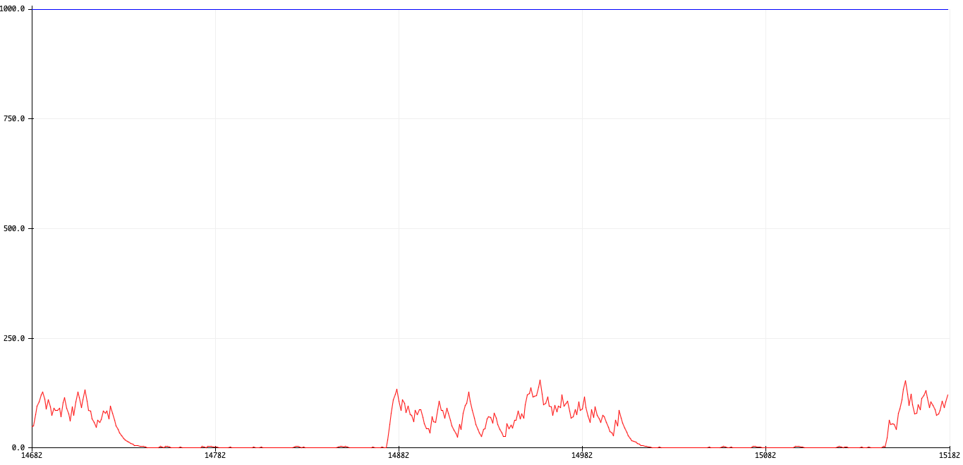
Then, I had the thought to switch them. Now the receiver was isolated, and my laptop powered the transmitter. Voila! Immediately the 60Hz pickup disappeared, and the spikes were now even larger. Win-win!
Receiver readings. Spikes are 1s, and flat bits are 0s. Note the lack of 60Hz noise: when it's flat, it's flat.
I think that the chassis/external cabling of my laptop allowed it to pick up a lot more noise than the isolated Arduino on its own. When the computer powered the receiver, the reciever gets a lot of that noise passed into it. However in this second config, the receiver seems to not pick up much noise on its own.
Interpreting spike clusters as bits
Through in-line capacitor vs. without
If you recall, I'm linking my receiver's analog input with GND with a high value resistor. I wanted to compare touching the analog pin directly with touching it through a capacitor. I expected to be able to charge the capacitor and sort of integrate the spikes into a more digital looking bit, but it seems to not help that much.
Receiver readings when touching through in-line capacitor
Receiver readings when touching analog pin directly
Using a capacitor first seems to increase the overall signal by a tiny amount. Or it could be selection bias! Either way, I don't think it matters too much.
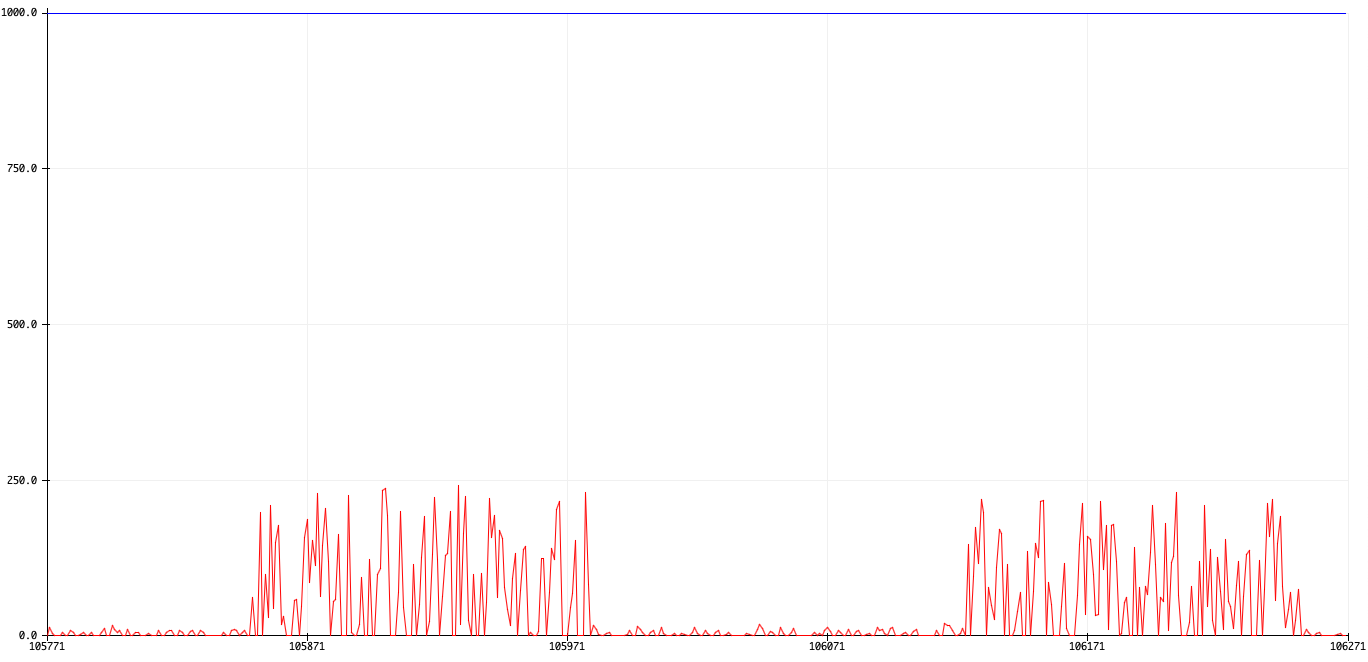
Software integration
I then tried to just keep a moving average of the analog readings. This is a 10-sample ring buffer that only averages the past 10 readings. The noise on the 0s has decreased a bit in the averaged output. The spike clusters are also now clearer, but at what cost? The highest point is now around 150 instead of 250. Not so bad. I'll probably choose a max filter instead to better approximate a logic signal.
Short-term moving average
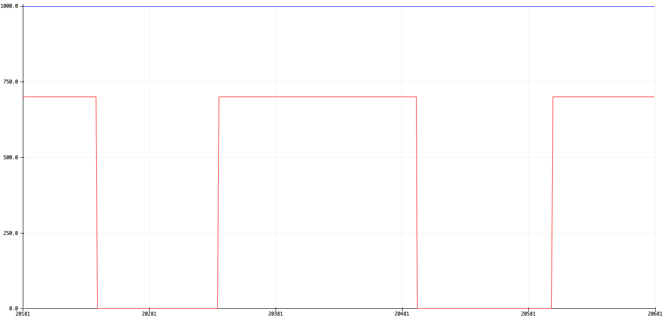
I also tried a counting filter which output 700 if there were more than 5 samples > 100 in the past 10 seconds, and 0 otherwise.
Boolean filter of (num samples > 100) > 5
Highest speed
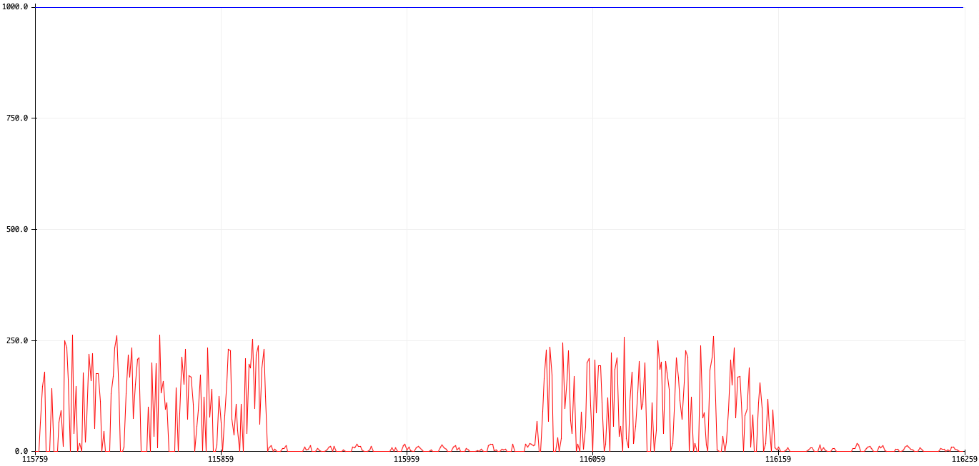
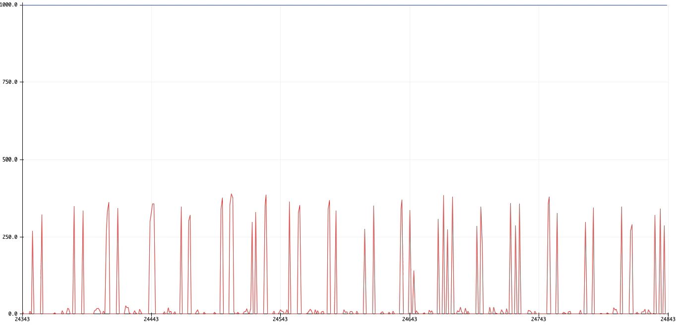
The fastest speed I tried was a bitrate of 50Hz. A pulse train was sent every 10ms, then not sent out for 10ms. Looks good, there are at least 5 received bits within each window, and I think a human would be able to pretty clearly differentiate between 1s and 0s.
50Hz train of pulses transferring between the transmitter and reciever
Conclusion and next steps
I just want to make it clear, this method sucks. It's really hacky, and the receiver needs to have a much better and faster analog-to-digital converter for it to properly receive the spikes. I'm trying it out with a better microcontroller soon, and we'll see if the spikes can be made even tighter. I want a data rate of at least 1000 bits/sec, and it would be amazing to hit 40 kilobits/sec since that's a typical RFID data transfer rate. But at least it works without a shared ground now!