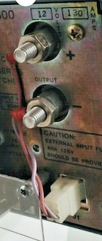
Measuring 150 Amps With A DIY Shunt
Published September 6, 2021
Hello everyone! Today I'm going to show y'all my testing of a high current, low voltage DC power supply.
Typical bench power supplies will go up to about 30V, and output 3A at most. For more powerful power supplies, their focus will usually be on voltage, going up to kilovolts at only a few amps or milliamps.
I recently had the need for the opposite kind of power supply, a high current and low voltage one, up to 200A at around 3V. I found this one on Ebay which seemed the fit the bill. Let me tell you all about it!
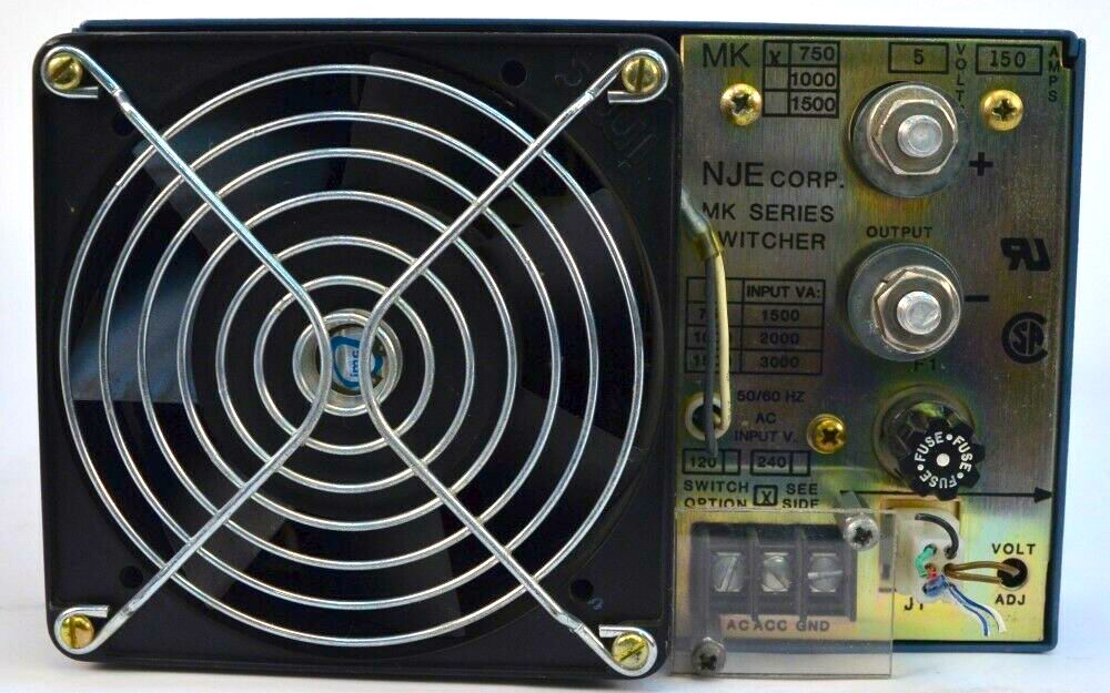
What could it be?
How do you make 200A?
Before I bought this, I had juggled a few alternatives. There are many sketchy ways you can generate huge currents. A few I considered were:
-
A) shorting out around 10 drone/RC car LiPos in parallel (burst numbers are higher, but about 20A sustained current per battery)
-
B) Rectifying and rewinding a microwave transformer to output 3V from the wall
-
C) Harvesting RAM power supplies from dead motherboards (Sketchy YouTube videos put this at 20A, 3V)
-
D) Buying a battery-tester power supply, which are at weird voltages (8V, 5V, 4V, 2V, etc.) but super high currents.
Option D beat out the others in terms of reliability, but those niche power supplies are quite expensive, even on eBay. Luckily, I found an older one that seemed to do exactly what I wanted.

The NJE Corp. MK750, MK1000, and MK1500 were power supplies at their eponymous wattage, which output anything from 2V to 48V at massive currents. The only datasheet I could find was this one, and there's not a ton of information on there (like what those 6 pins are for). But I needed this power supply, so I went ahead and ordered it.
Voltage Testing
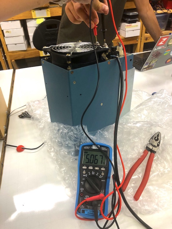
The first thing I checked was the voltage. After wiring the AC, ACC, and GND pins (3 prong power), I plugged it into a wall meter and checked the output. It looked good, almost perfectly 5V. With no load, the power supply drew around 70W, or 0.5A from the wall.
MK750 outputting 5V, as it should
Current Testing
What I really wanted to know was if the MK750 could output the massive currents its manual had promised. This was a bit trickier. I could have used a clamp, but I didn't think of that. Instead, I watched an ElectroBOOM video about DIY current shunts and decided to use one of those.
Really, a DIY current shunt is just a wire. At 5V, to output 150A you need a load of
$$ 5V/150A = 0.033Ω = 33mΩ $$
This is usually the resistance of a few feet of wire. Mehdi talks about how multimeters suck at measuring low resistances, but they are good at voltage. I cut a random length of a random wire off the wall, and passed 1A constant-current through it to find the resistance. The measured mV corresponded directly to the mΩ of the wire.
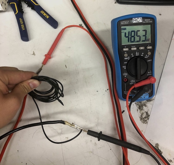
This bit of wire happened to be around 48mΩ, which was nearly perfect. However, just before I plugged it in, I realized that the entire output 750W of the MK750 would pass through this tiny 18 AWG wire and vaporize it instantly. Immediately I threw the thin wire away, and went foraging for some thicker power wires.
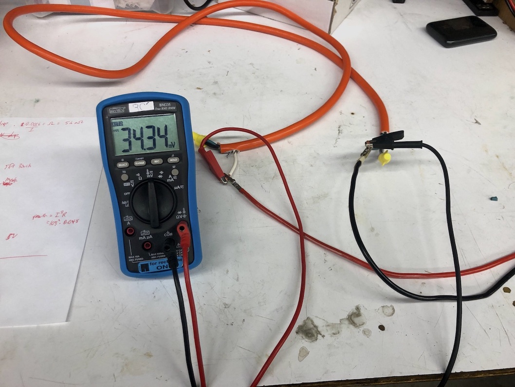
We cleaned the club a few days ago, and had thrown out some chunky orange power cables. Each cable had 3 conductors, so I took a length of this and crimped alternating ends together to make a triply long cable in the length of one. I did the same test as before, passing 1A through the combined cable. This resistance turned out to be actually perfect, at 34mΩ.
Using the 3-wire shunt (34mΩ)
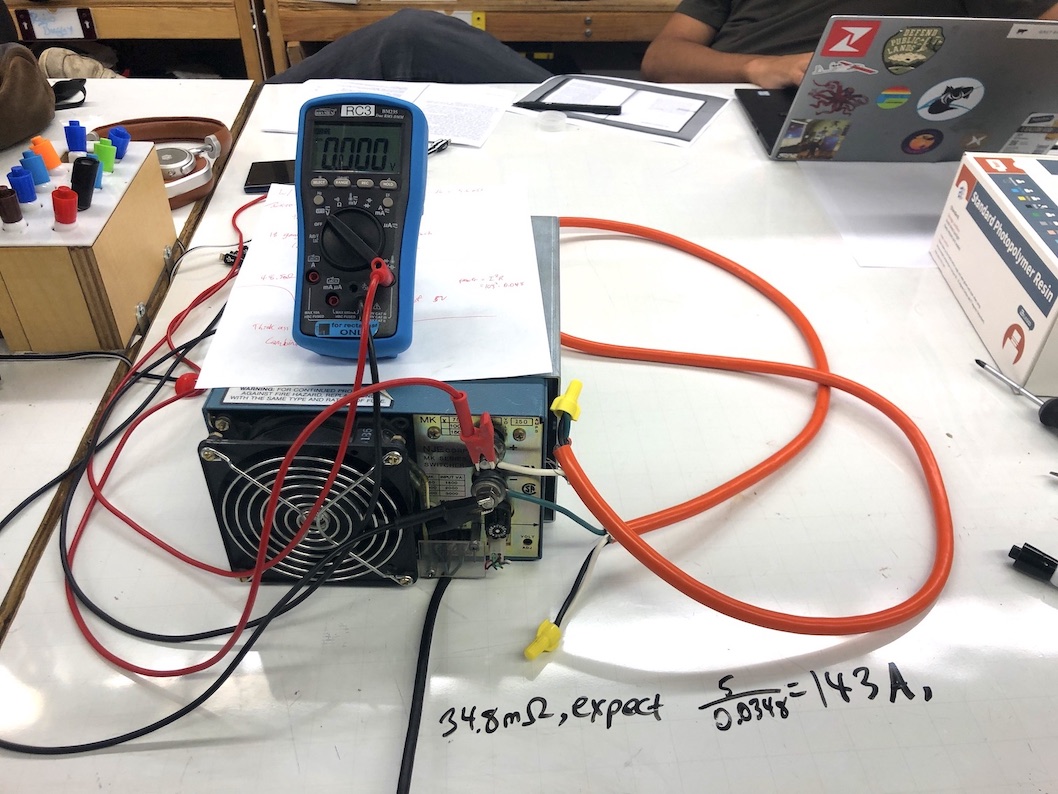
I connected our shunt to the power supply, then clipped my multimeter to the output. I'm measuring voltage to get the current. Since Ohm's law always holds, if we already calculated the resistance and then measure the voltage, we have everything we need. Time to plug it in!
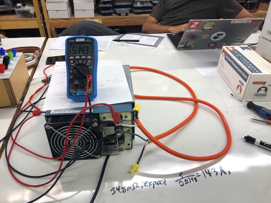
And the MK750 delivers! Across our 35mΩ wire we see a drop of 5.14V, which works out to $$\frac{5.14V}{0.035Ω} = 147.7 \text{Amps}$$ Woohoo! Almost exactly 150 amps at 5V. The readout from the wall meter said around 900W, so approximately the baseline 50W + 150Ax5V. Not bad for efficiency.
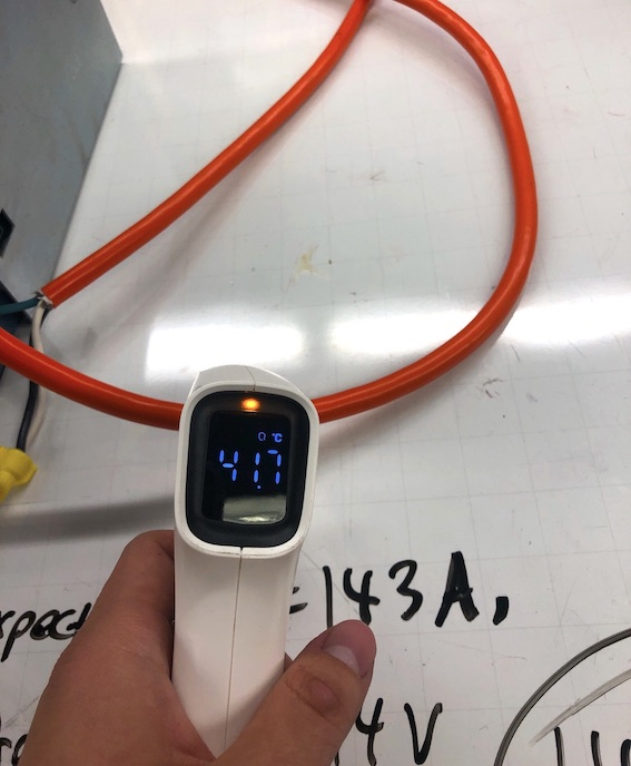
Oh, and the wires got HOT. I only left it on for a few seconds for safety, but even then the thermometer said the wire got over 100F. Crazy!
Using a 2-wire shunt (23mΩ)
I wanted to see what this power supply was really capable of. I had avoided using a shunt lower than 33mΩ because I was afraid that shorting out the power supply would break it. Thinking further, I realized that 33mΩ is already considered a dead short in any other application, so it probably wasn't a concern.
In our 3-stranded shunt, each wire was around 11mΩ. I moved the crimps so that it only used two wires, for a new shunt resistance of around 23.2mΩ. I reconnected everything to this smaller shunt, and switched it on.
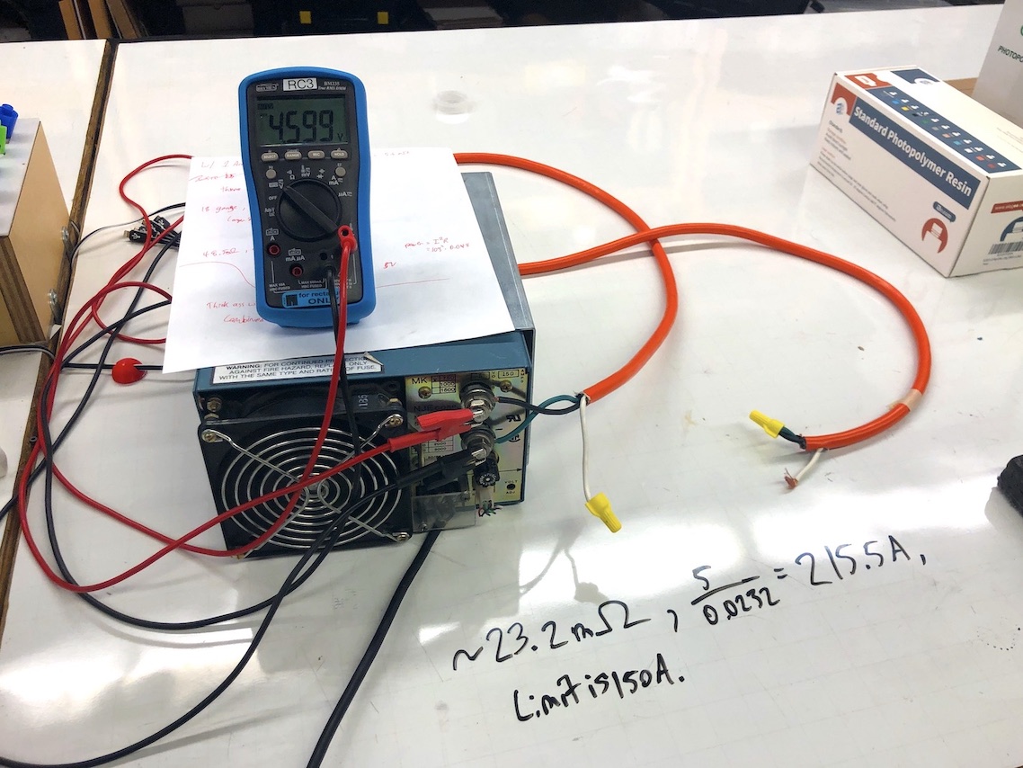
As expected, the output voltage dropped a bit to compensate for the short. However, the voltage reading on my multimeter immediately started shooting up, beginning at 4.3V and climbing to 4.9V in the space of a few seconds. I assume this is from heat increasing the resistance of the wire, and shut it off quickly.
Using the initial reading of 4.3V, Ohm's law says the MK750 output 185A at first, and a clamp meter agreed at around 170A. The wall meter read 1120W during this test.
Closing thoughts
This power supply is amazing. Unfortunately, the NJE Corporation just filed for bankruptcy last year (2020), so I don't think we'll be seeing many more power supplies where that came from.
It also smells weird, but that's completely fine given its the excellent performance otherwise.
Cya next time!
May 8, 2024 Update
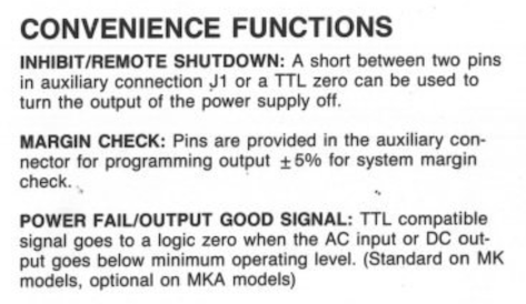
A reader emailed me asking for the pinout of the auxiliary J1 connector on the front panel of the power supply. I never had use for these features so I did not know, but he was dedicated enough to order a manual and kind enough to send me a picture:
The pinout of the J1 connector on the NJE MK750/MK1500 high current power supply

These pins correspond to the functions mentioned in the 1-pager manual I have above.
And the sense pins are supposed to be connected to the outputs like so (I think to monitor the output voltage).
From random eBay listing
