Infoglobe Tutorial Pt 1 — Hardware Prototyping
Published October 1, 2022
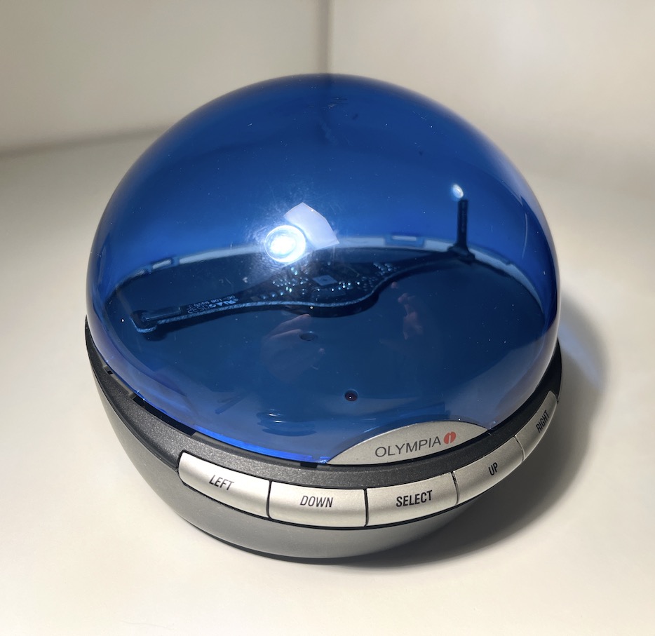
Hello! I'm writing a tutorial on how to hack your own Olympia Infoglobe. This first part just tells you all the wires you'll need to cut or connect in order to make it display custom messages.
caption
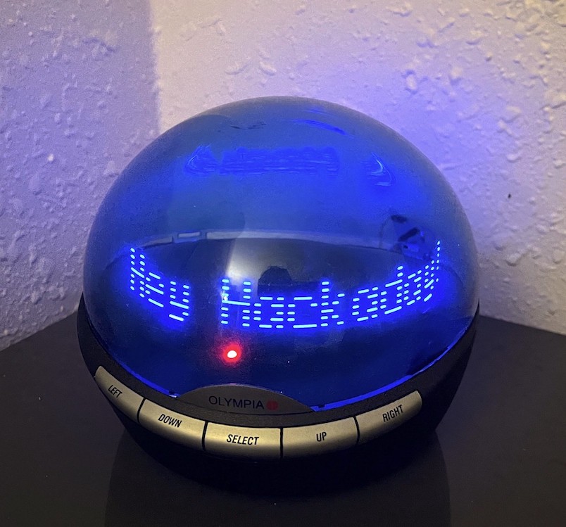
If you don't already know about the Infoglobe (surprising considering how I won't shut up about it), it's a caller ID system from the turn of the millenia which displayed who was calling your quaint little landline phone. It could also store messages that people left you, and display holiday messages. Overall, a cute little device!
Today, the humble Infoglobe has been rendered obsolete by the modern smartphone. With no landline resurgence in sight, we're going to hack the Infoglobe to show custom messages and give it a second life as a weather station or some other mundane job.
Let's start!
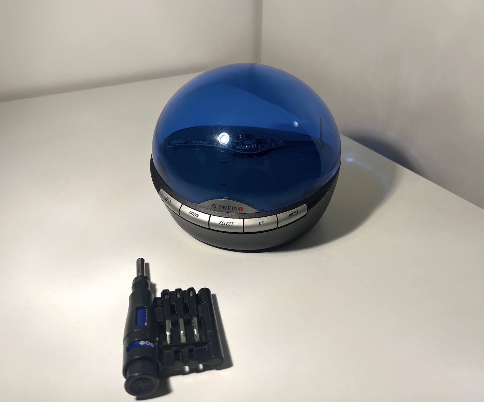
Tools
You'll need the following things
- 1x Infoglobe
- Philips head screwdriver
- wire cutter
- soldering iron + solder
- 50-1kΩ resistor
Since I already did this hack, I have only photographed two of the tools. Please use your imagination for the rest
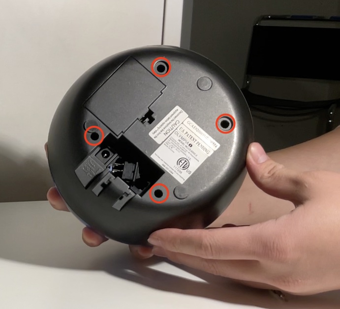
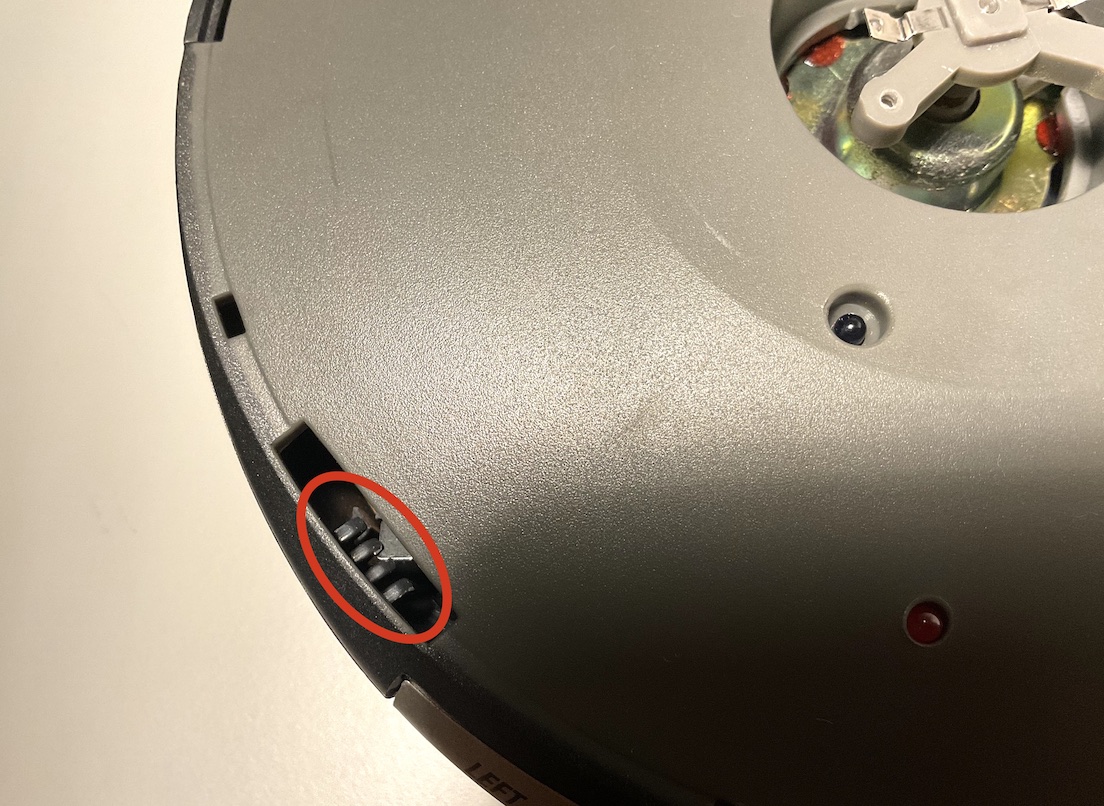
Step 1: Remove the screws from the base
Pretty straightforward. There's 4 Philips-head screws in these 4 dark holes. They're kinda deep in there, so get a long thing screwdriver. Nothing will happen when they come out, but it makes the next step easier.
The four screw burrows, helpfully circled in red
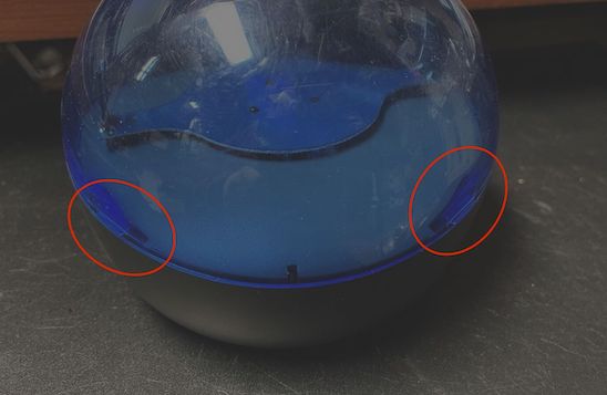
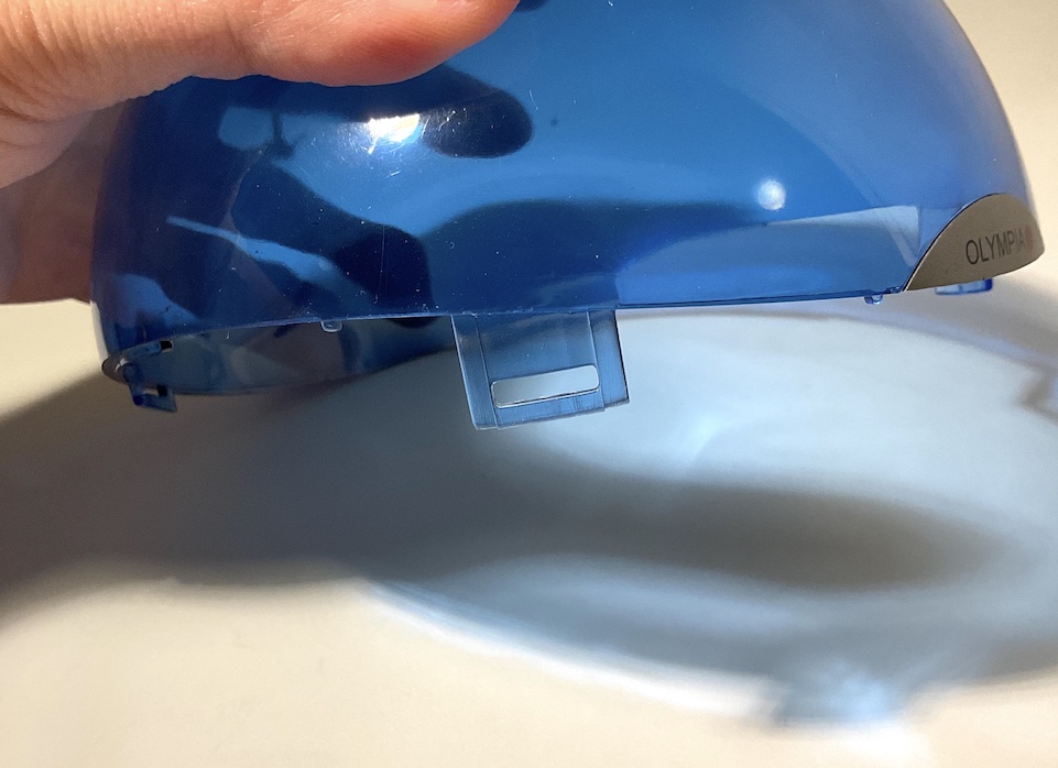
Step 2: Remove the clear blue dome
Now we're taking off the top and getting to the insides. The top is held on by four latches you can see from the outside on the edges.
Latches visible from the outside (pic from eBay)
Inside, they have a little notch going from the wall radially inwards
Inside the base, there are notches that go towards the center
The top part has these seatbelt-like shapes that line up with the notch on the inside.
And on the top part, there are latches that extend into the body
Careful!!
I won't lie to you: getting this thing off is kinda hard. You feel like you're gonna break it on accident, and it's a sphere so it's hard to hold on to, and will definitely break when you drop it. I recommend sitting on the floor or hugging it when you're wrestling the top part off.
You'll want to pick one latch to start with. Right above the latch on the blue part, pull inwards and pull up at the same time. Hold the base tightly with your other hand, or hug it with your arm. A wedge/screwdriver is unlikely to help. Here's a video of me getting the first one out.
Funnily enough, I'm wearing a Dome shirt as I open this dome
The rest of the latches get easier after the first two. Same technique, just pull in and pull up at the same time.
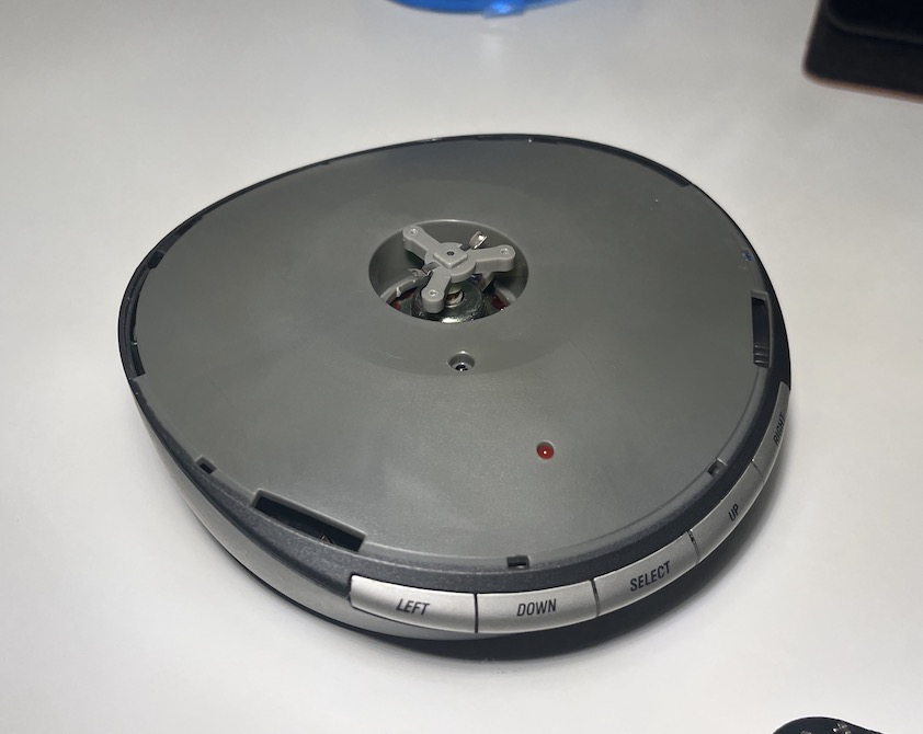
Step 3: remove the propeller
Once you're in, the grey part will be loose, but still held in by the spinning arm of the Infoglobe. We'll have to take that off. Just use your screwdriver to remove those 3 small screws. The propeller is spring loaded, so maybe unscrew all of them a little first so the first one doesn't bounce out and get lost
Note the square center peg and the triangular screw arrangement - automatic alignment!

Remove both the propeller and the grey plate and set them aside.
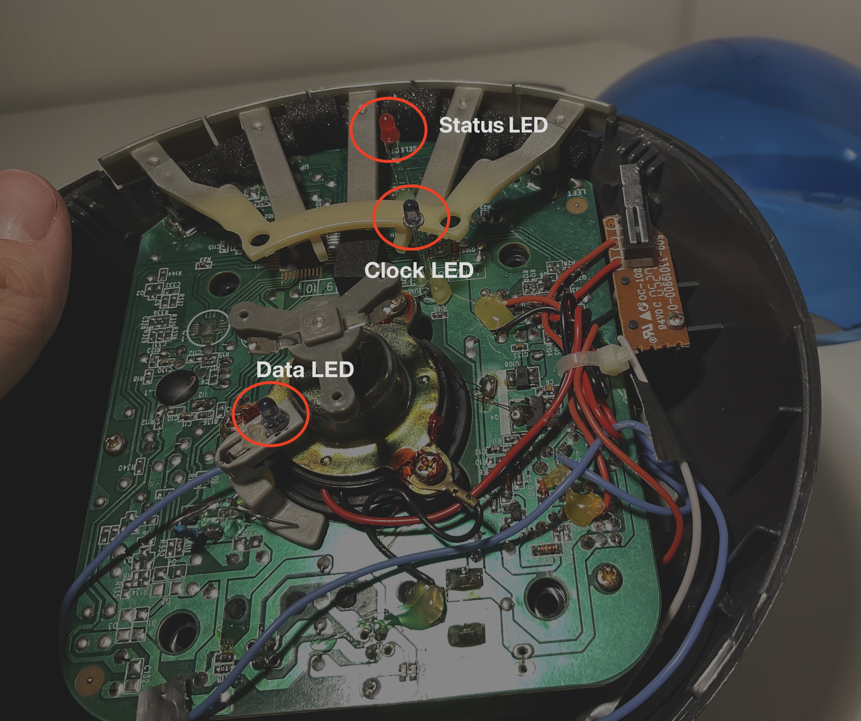
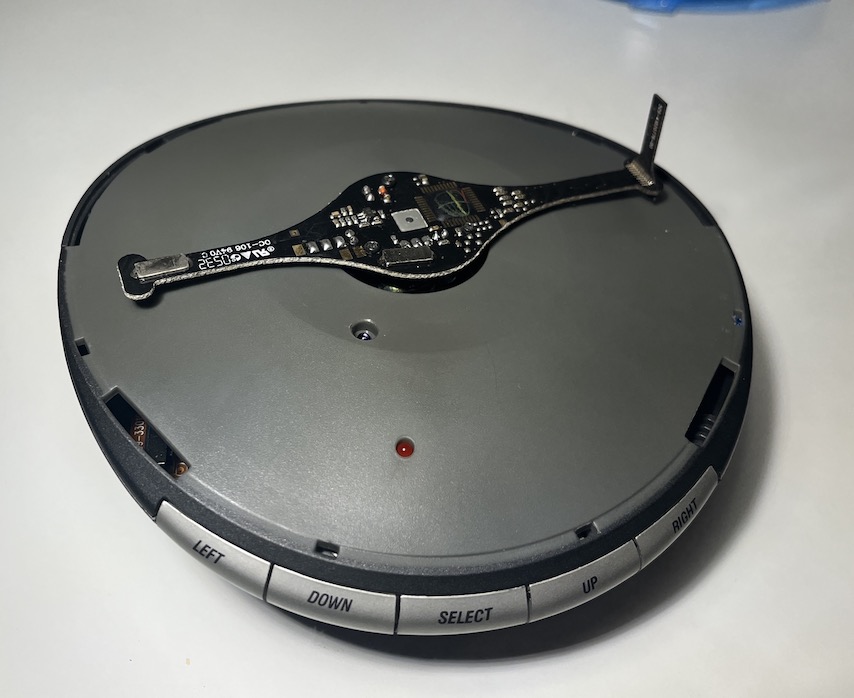
Step 4: Hijack the Infoglobe's data LED and add a current-limiting resistor
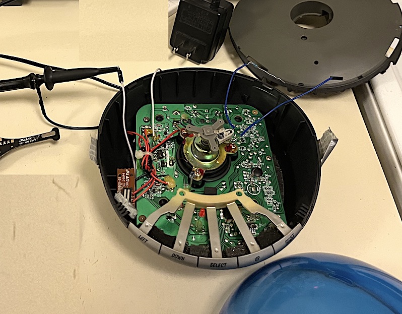
There's 3 obvious LEDs once you're looking at the circuit board. One is red, this is just a power indicator. Of the two other light-blue ones, the innermost one is the data LED.
All LEDs inside the infoglobe, labeled
Previous tutorials have made circuit boards that integrate into the infoglobe, allowing it to continue displaying the phone stuff you wanna see plus cool custom stuff. This is why past projects have had such complex setups. I say why bother? The data LED has two wires like any other LED, and if we cut them then we can write whatever we want.
There's two ways about this. You can either cut both legs of the LED and solder on new wires that run to the outside of the infoglobe, or you can just cut the positive side of the LED and connect the grounds of the Infoglobe board to your microcontroller.
Either way, two wires get added so it's really up to you. I started with the single wire and joined the grounds first because I knew I wanted to power my microcontroller off the infoglobe power eventually, and it made prototyping way faster.
The two-cut approach hijacks the entire data LED. The LED's positive side is on the left
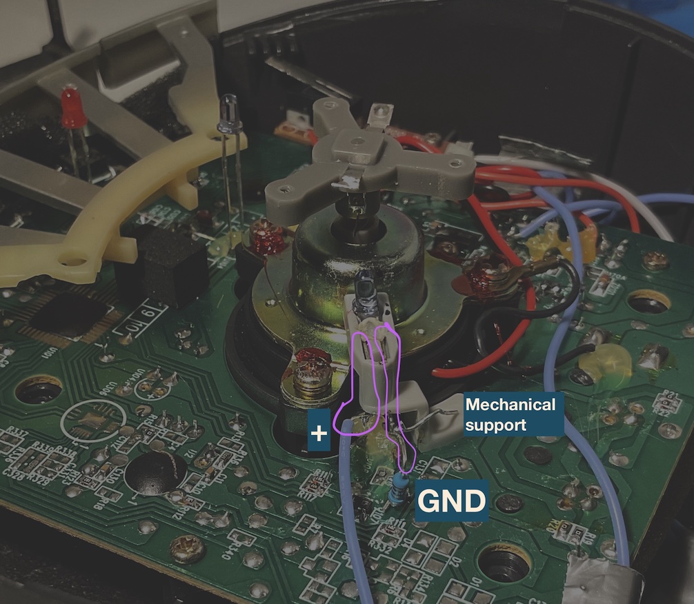
The one cut approach, hijacks only the power wire (left) and requires you find ground somewhere else (anywhere connected to the right wirse is fine)
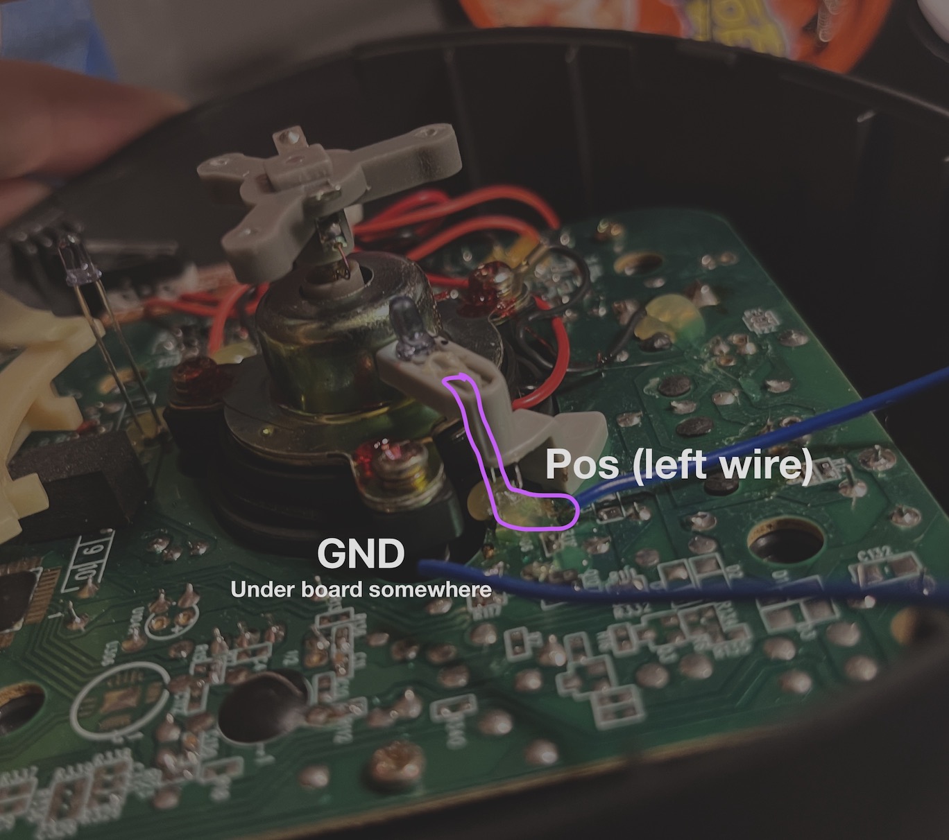
Run those two wires outside of the casing and connect a resistor in series so you don't blow out the Infoglobe's infrared LED.
PLEASE CONNECT A SERIES RESISTOR TO THE DATA LED LINE BEFORE USING IT, OTHERWISE YOU RISK BURNING OUT THE LED!
Testing the Infoglobe without putting it back together
If you wanted to plug in the infoglobe with all the plastic off, it'd probably be dangerous for both the board and you. It just takes a hair caught in the rotor to ruin your Infoglobe and hair and project all at once. But it sucks to put it all back together, and there is a way to be relatively safe without doing that.
1) Put the grey piece back on. The alignment is a bit tricky but it should drop right in
2) Then place the rotor back on the center section and screw it in. Make sure you screw them all in a bit simultaneously, since there is a spring under it.
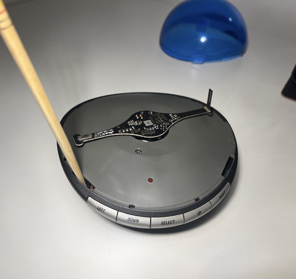
3) Get something to fool the safety switch, preferably nonmetal
This limit switch needs to be taped or pushed down
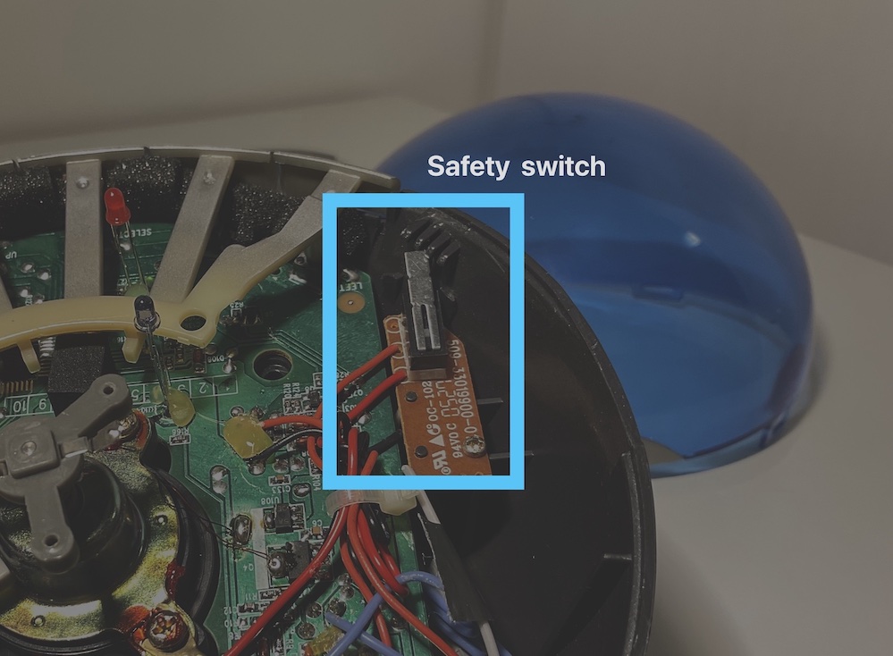
Chopstick works for depressing it
The top dome can also be placed into the slots without clicking down, but still low enough to trigger the safety switch. This is probably the safest way to do it.
The lid also works for triggering the safety switch, but this is the only method that is actually safe
4) Plug in the infoglobe power, and the rotor should begin spinning with no words appearing
To change the insides requires at least unscrewing the rotor, but luckily you won't need to do it much at all.
Final setup
At this point, you should have an Infoglobe with two wires coming out of it. I originally used F jumpers as the wires to the data LED, then plugged into them using an external Arduino.
Picture of the Arduino setup I originally worked with, Arduino not in-frame
Later when I was sure the code worked on Arduino, I moved to using an ESP8266 microcontroller. It's the little square with a blue light in the picture below.
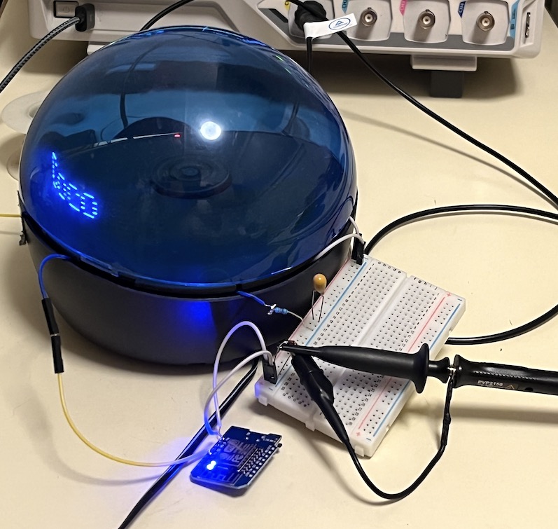
Since the ESP has no headers, I'm using a breadboard to connect the ESP to the data wires. Again, the LED's wires you've added will just run out from under the shell of the Infoglobe, and they safety switch can be engaged using the top dome despite the wires preventing it from closing fully.
There is some more hardware on the breadboard than I'm letting on, but that will be covered in Pt 2.
Conclusion
There's a few more steps if you want to integrate the infoglobe with your microcontroller, but that's for a later tutorial. Now you've gotten a connected LED. Time to write some messaging software!
If I haven't published it and you want me to get on with it, just shoot me an email and I'll add it to my very relaxed schedule.
Update 10/13: There's a part two here!