Infoglobe Tutorial Pt. 2 — Hardware Integration
Published October 15, 2022
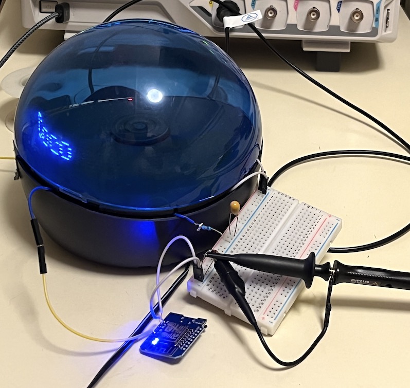
Hello! We're still hacking the Infoglobe. This post is about internalizing the external electronics we were using in the first tutorial, as well as powering our microcontroller using voltage from sources inside the infoglobe so we don't need two power lines.
As you may remember from last time, we wired up the data LED and ran the wires out of the infoglobe, where they were connected to an ESP8266 via breadboard. This is a great testing setup for the Infoglobe because we can fine-tune and measure the data we're sending to control the Infoglobe's display as we're figuring out the IR protocol.
From here, I'd recommend fellow Infoglobers to first write the software to control the Infoglobe, just in case there are any repairable hardware problems that can be detected early. Assuming you've done that or are using known-working code, we'll proceed with internalizing the electronics
Our testing setup from tutorial 1
Tools
You'll need the following
- 1x Infoglobe, opened
- ESP8266/ES32 or other small microcontroller
- Soldering iron + solder
- Good air filter or fan
- Dexterity
- Various passives
- Thin or flexible wire, preferably both
- Power switch, small (optional)
- Diode (optional)
- Big capacitor (optional)
Steps
- Prep the microcontroller and its new home (µcompartment)
- Prep compartment
- Attach the flyback diode
- Attach the filtering capacitor
- Run power lines to our microcontroller
- Find ~5V using a multimeter
- Run wires to the µcompartment
- (optional) Make an in-line power switch for the microcontroller
- Run data lines to our microcontroller
- Connect LED to ground with a resistor
- Solder new wire to the LED's high pin
- Run data line to µcompartment
- Wire up the ESP
- Melt a hole in the battery compartment
- Feed wires through the hole
Step 1: Prepping the microcontroller
First we're gonna prepare the microcontroller for implanting. The main thing we're worried about is power — it sucks to have to plug two power cables in to use a consumer device, so we're hijacking the 5.6V line from within the Infoglobe itself. The only problem is that it's the motor power, so it's noisy and has kickback. Feel free to skip ahead if you know all this already.
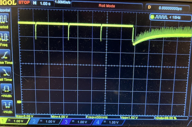
The motor's source is not the best. Starting up the spinning rotor requires a few kicks sometimes, evidenced in these sharp voltage drops on the scope. And even after the motor begins, there's noise on the voltage spanning almost 1Vpp. However these are tameable.
Motor noise and startup behavior
Motor protections
A motor is a set of coils that magnetize when current goes through them, allowing them to push off a set of permanent magnets in their center and generate the torque that they're known for. Whenever we turn a motor off suddenly, we essentially stop pushing current through a large inductor, their coils. This inductor then tries to preserve the current going through it by flipping the voltage across it. In practice, this means turning off a motor briefly creates a massive spike of both positive and negative voltage.
Motor turn off creates a big spike of voltage
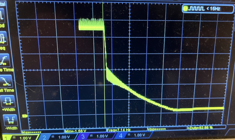
This is called kickback, and it can damage sensitive electronics like your microcontroller. To protect our ESP against kickback voltage, we connect a diode going from GND to V+. In case GND ever exceeds V+, it'll leak through the diode before it has a chance to go through our microcontroller and destroy it.
Smoothing motor voltage
Besides quickly fatal problems like kickback, I was also concerned about slowly fatal problems. Like that the noisy voltage of the motor would mess with the internal timings of the ESP and prevent WiFi from working properly.
We are taking the stardard solution to this, which is to use decoupling or filter capactiors across V+ to GND. Due to the size of the noise, nothing worked until I got to massive values of C. Here I've placed a 220uF tantalum capacitor across the V+ line and GND halfway through the oscilloscope trace.
Capacitor filtering motor noise down to half the amplitude
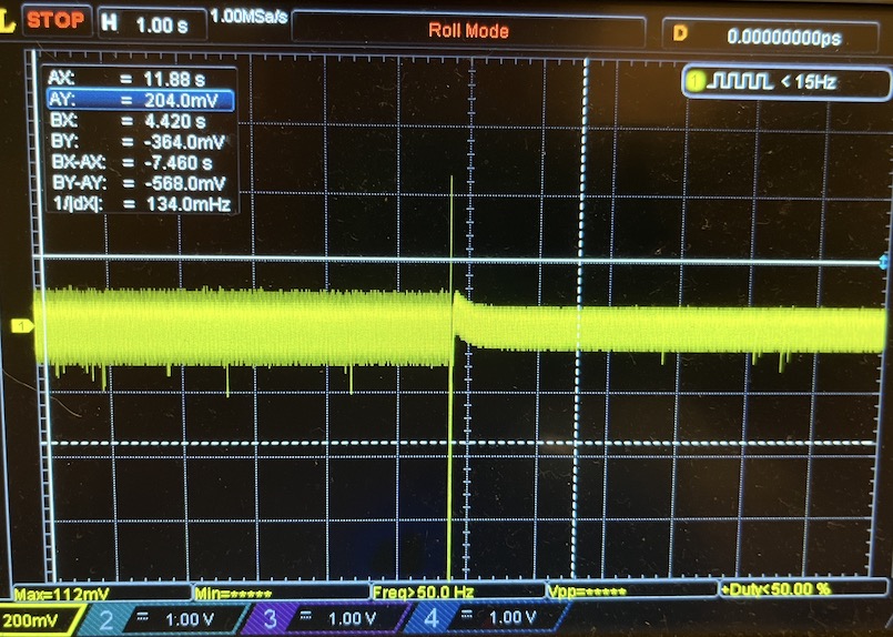
You can see the noise drop from a 200mV brick line down to ~100mV. Although it's not super significant, I left it in because it didn't do any harm and definitely does help smooth the noise.
Done setting up the microcontroller?
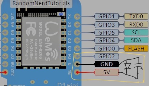
It should look something like this:
schematic of microcontroller for the infoglobe.
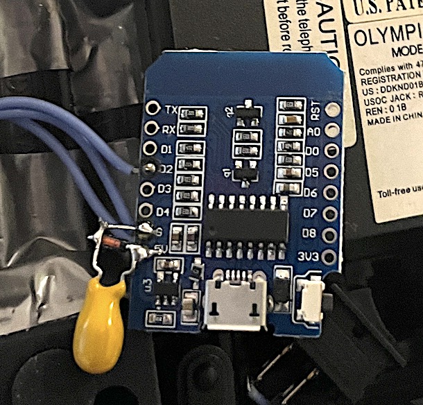
View of the bottom of the infoglobe's new brain, the ESP8266
Finishing touches
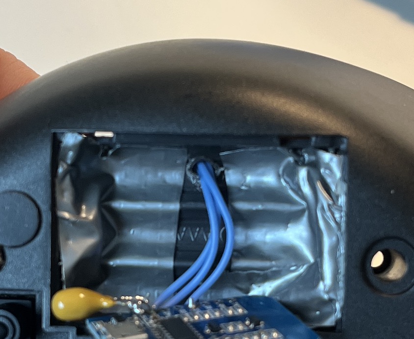
Once you've wired everything, tape up the inside of the AAA backup power supply so we can put our ESP in there without shorting it out.
Why are all those funniny blue wires going though the hole for? Patience, my dear friend. We're getting there.
Step 2: Finding power on the Infoglobe board
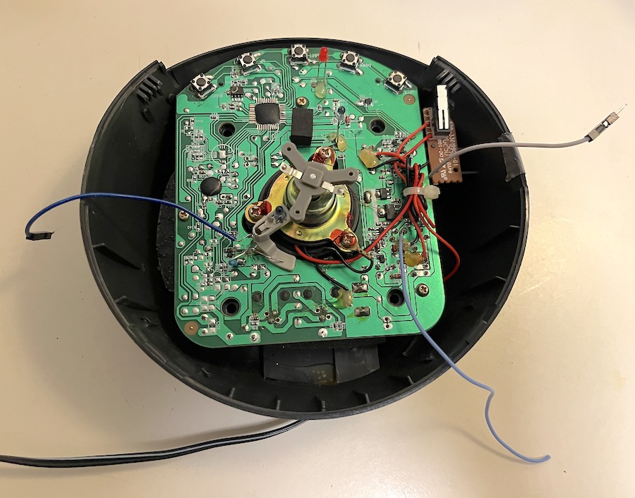
When you first open the infoglobe, you get to see its beautiful, unmarred circuit board. We're gonna mess with it immediately.
The power wires are the red ones. Yes there's 3 sets of red wires wrapped together. No I don't remember which is which.
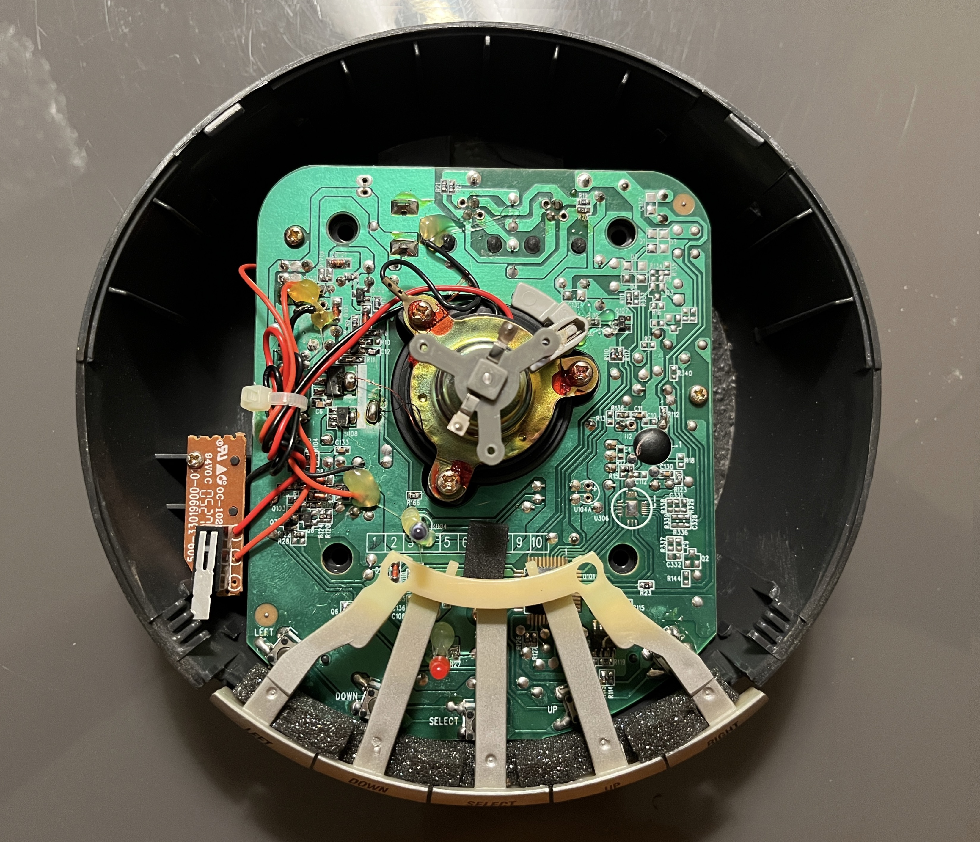
We know that the motor probably gets its power from one of the red wires. The only problem is, there's three of them and they're all super tangled up. If we look closely, we notice that two of the red wires go to the bottom of the limit switch, the very piece that controls the motor turning on! As it turns out, those ARE the power wires, you just need to figure out which one is "after" the switch (off when switch off, etc.), then connect our ESP's power wire to it somehow.
Stripping out a section and soldering works, but alternatively, you can use the power wire to do a continuity test and find regions on the board that are connected to it. One probe on the power wire, and with the other probe you just start testing random pads on the infoglobe board.
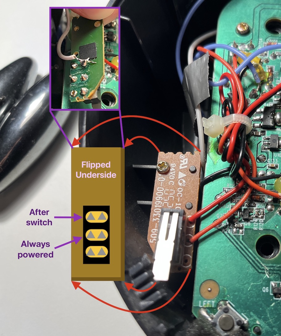
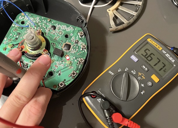
Here's where I broke out the voltage. Under the safety switch you can find the V+ connections, both before and after the switch.
Location of the 5.6V line we'll be using. "After switch" comes on when the safety is down.
If you want to check, you can plug the infoglobe in and check if the motor supply voltage is what you want. It should sit at ~6-6.3V when the safety switch is off, and drop to ~5.6V with the rotor on.
Supply voltage at 5.6V, rotor visibly spinning
With the safety switch untriggered, supply voltage is over 6V

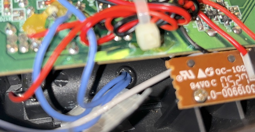
Once you've confirmed that the power lines are giving you what you want, go ahead and solder a long wire to the V+ point. Also solder a similarly long wire to a GND point of the board. You can find these all over, here's the two I used.
I used the left one for power ground, and the right one to ground my data LED
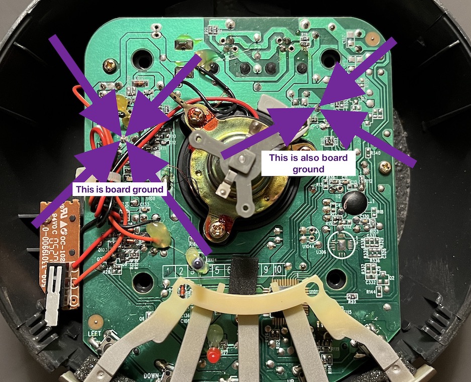
At this point you should have 2 wires coming from the left side of the board connected to power and ground, with long enough wires to push them into the microcontroller's compartment.
Step 3: Data routing
All that's left is to reroute the data wires that we made earlier.
Earlier when our computer powered the microcontroller, the microcontroller didn't share a ground with the infoglobe so we had to cut both power and GND on the infoglobe's data LED. Now that the microcontroller is sharing the Infoglobe ground, we can ground the LED near where it stands and just run one wire to the microcontroller, avoiding another messy wire.
If you look in the ground pic above, you'll see the right connection point is right beside the data LED. I soldered the right leg of the LED to that spot on the board through the current-limiting resistor we had on it before.
Picture of the right leg of the LED (ground side) connected via resistor to ground
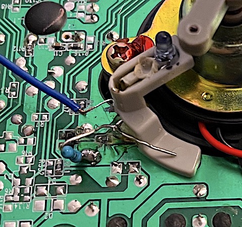
Alternate view of the LED's ground side
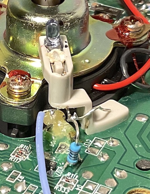
Now we have the LED grounded, we want to connect a longer wire to the LED's positive side and run that wire towards our microcontroller compartment. I just cut my old wire and soldered on a longer bit, which can be seen in the pictures above.
After you've done this, the data LED should have one long wire coming out of it and the power area should have two. Picture below, but the wires need to be elongated to reach the compartment comfortably.
Completed wiring overhead shot, but the wires are all too short
Step ? (optional): Add a power switch
EDIT - I don't think this mod is necessary anymore. I was worried that powering the ESP with my computer while it was still connected to the motor's power would run 5V to the motor and and make it spin, or else damage the motor by underpowering it in some way. I checked the resistance across the motor and it seemed pretty high, so I'm no longer worrying about this.
Since I wanted to be able to change the code on my ESP after putting it all back together, I connected the microcontroller to power through a little click switch that I left in the bottom. I had to burn a second hole through the casing to do this, but I think it's necessary
Power switch for ESP
Step 4: Finish routing the wires to the compartment
You'll need your soldering iron again for this part. The battery compartment at the bottom of the infoglobe does not have a hole to the inside, so we're going to add one by melting the plastic with our soldering iron. If you have a drill, it'll work but probably not well.
The spot I chose is next to the safety switch on the left side of the Infoglobe, and is the only side of the battery compartment visible from the top without removing the PCB. Clear the area of wires and make sure the other side is clean, then get to a soldering filter fan. You'll just push the soldering iron tip into the plastic casing slowly, and voila! A hole for our wires!
Internal hole for wires going to the microcontroller
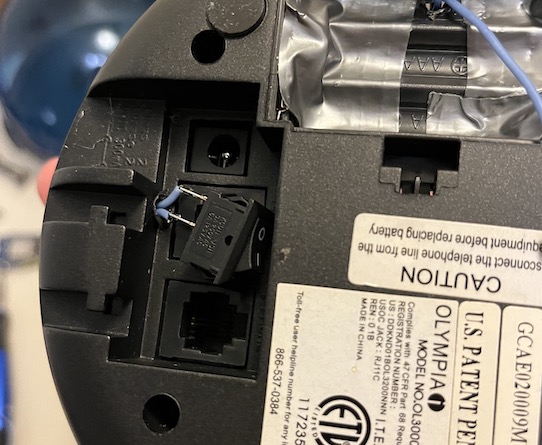
Corresponding external hole
We are gonna push three wires through this hole, mine happened to all look the same so I had to mark each one so I could tell them apart. On the other side, you'll solder the power to 5V, ground to GND, and the data line to D2 or whatever pin you're using in your code to control the infoglobe.
Your microcontroller should sit nicely if it's got the Wemos D1 Mini shape.
Step 7: Put everything back together.
Secure the wires internally, then put the grey shell back on, then screw the rotor back on, then put the dome back on.
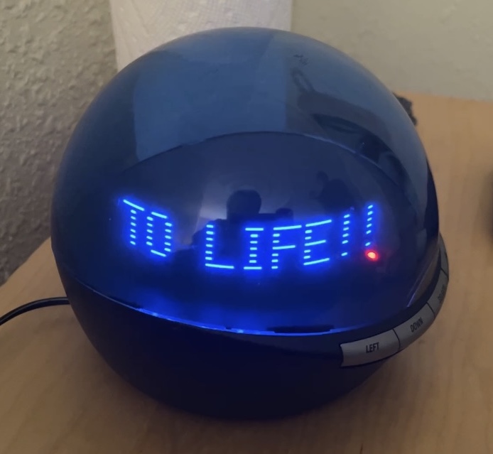
And we're done! You are now the proud owner of a modded Infoglobe. Now get out there and make it say some cool stuff!
Cya later!
Let me know if I've left out details or you need any clarification, my email is listed above.