Putting together Myo3, the 3rd iteration of my EMG sensor
Published November 22, 2020
The PCBs came sometime last week, and I got the rest of my resistors and passives today. Time to construct!
My housemates still are quarantining, so I was trying to stay out of the hallways and common areas (like the workshop we have -.-). I moved all parts into my room, but my desk definitely wasn't bright enough. We make do though. Big shoutout to HTMLBom for enabling my board construction, it's a super useful plugin for KiCAD and you should get it immediately.
Cool parts of the board:
-
Using the TLV2624 to create a virtual ground from my single-sided power supply. It's the laziest way to do it, but I never claimed to be able to do power well.
-
This board uses the input stage op-amp with optimal noise, assuming dry electrodes (1 MΩ resistance). This is the LME49721, with 4nV/rt(Hz) voltage noise and something like 1 fA/rt(Hz) current noise. Funnily enough, it's an audio amp, with lots of Thad graphs all over its datasheet. If it works it works!
-
I made two boards actually. After the initial LME49721, I switch to an op amp that can source a little more current and drive more capacitance (for the analog filtering).
- One board uses the OPA4202, which can drive INFINITE capacitive load. I chose it because it can do that.
- The other uses the POPA4991, which can only drive 1nF cap load at gain=1. I chose it because it only needs supply voltage similar to the LME49721, meaning I can use a LiPO to power the board instead of trying to source 5V somewhere.
-
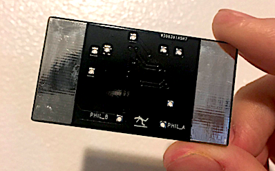
It has pads on the back! This allows you to strap it directly to your arm to measure muscle signals. I got really sick of putting those 3M red dot electrodes all over myself, especially when they left glue residue all over me.
-
Guard ring 😎 (really it's kind of useless cause I didn't put it on the back as well, but it's the thought that counts (also, I don't really care about input bias current, up until 1 pA or so. Then it generates (G=100000)*1pA*(1 MΩ skin impedance) = 1 V offset at the end of the circuit, which would definitely pin it to the rails!))
Problems I ran into:
-
TSSOP 16 pin is super tight, it's hard to spudge properly (took me 3 tries).
-
I only had 0402 and 0803 parts, but guess what footprint size I decided to use?? :)))))) Luckily both work, the 0402 is really stretching to reach both pads and it doesn't tack as well to the solder paste, but it still works.
-
Also I shouldn't have picked a black solder mask, I can hardly see the 0402 resistors
-
I didn't have 220nF capacitors at all, so I sorta just... skipped it. Luckily, if you know the board, you can just decide whether or not you need a part. This particular one was part of a passive high pass filter, which came before a 2nd order active high pass at the same cutoff frequency. I just removed the cap and resistor, and bridged the resistor pads afterwards.
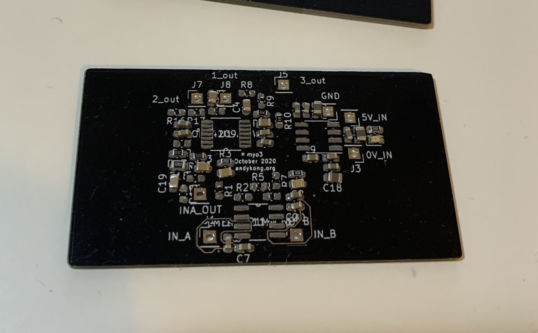
Here's some pics!
Front after spudging
Back of board, with integrated pads
Gonna spec its noise and stuff soon!