Myo3 EMG sensor initial tests
Published November 26, 2020
I finally got around to powering on those EMG circuits I made.
Initial test
For an initial test of any circuit, I was taught to flick the power on and then immediately off. If the current indicator spikes, you know there's a path error, but it might not have burnt out the chip just yet. The idea being not enough power has passed through and messed up the delicate silicon in the chip. I did just this flick trick, and saw a massive current jump immediately :(.
I wracked my brains and traces for any mistakes I could've made in the wiring, but failed to find anything. Went back to the schematic, because maybe I had put in a path to ground somehow? Maybe switched out a bypass capacitor for a bypass resistor? I saw nothing of the sort.
A day later, I looked again at the behest of a friend helping me debug, and found this:
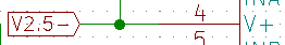
Flipping the positive and negative supplies on anything is a big no-no
Fixing the problems
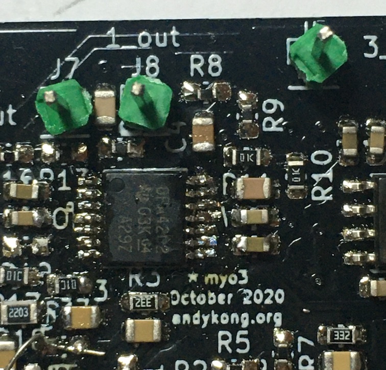
Luckily, I had only messed up on one chip, a quad op-amp. I was able to just rotate it 180° and have all the same inputs and outputs. Unluckily, it was on the TSSOP|16 package. Excuse the flux everywhere, but here's the chip after fixing.
I also had no solder-wicking braid, so had to fashion some out of a flux pen and some stripped, stranded wire. Worked surprisingly well, but went through wire rather quickly compared to the braided stuff. Wire's cheap anyway.
Actual initial test
My function generator set to 100 Hz sine wave has a minimum output voltage of 20 mV peak-peak. I'm trying to measure a signal approximately 5 uV p-p in size, so I made a voltage divider from a 50kΩ and 10Ω resistor. 20 mV becomes around 4 uV, and I have a high resistance measuring path to simulate the skin impedance.
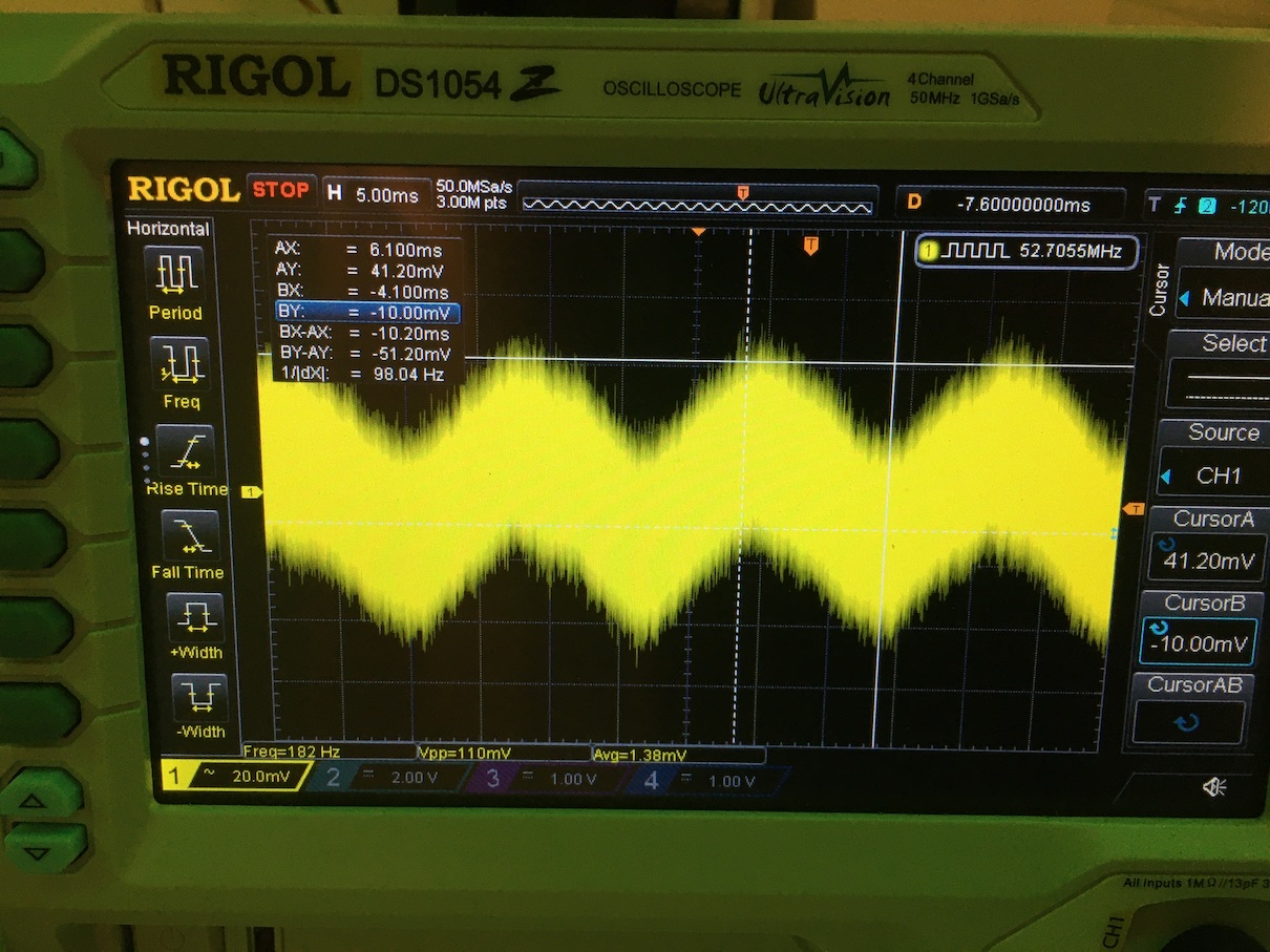
First stage, G = 1000
The sine wave first visibly appears on the output of the INA (first stage) at around 20 uV p-p, standing at around 50 mV p-p for a total gain of ~1000. This is pretty good, but the next stage is saturated at 12 Hz. I believe I accidentally made an oscillator by being greedy and adding gain to a perfectly good 2nd-order Sallen-Key high-pass filter, but I can rectify this by messing with some resistors. ~
Shorted inputs noise
With inputs shorted with a wire, there's a little bit of 60Hz line pickup. That aside, the noise p-p appears to be 70 mV after a 1000x gain, putting the initial, full spectrum noise at 70 uV. As it stands, much of the signal is very high frequency noise. After the RFI/EMI filtering it should be much better since the bandwidth gets heavily reduced, down to around 300Hz.
I'll post further updates after I fix the filters. No board ever works its first time, but it gets there if you want it to!