Myo3 Noise Specs
Published November 29, 2020
Today I tested the third iteration of my DIY EMG sensor.
Fresh myo3 boards from the oven
Measuring the total gain
My function generator only goes down to 20 mV p-p, I'm using a 50kΩ and 10Ω resistor to make a voltage divier to divide my input signal by 5000.
I'm using a 200Hz sine wave, since that's the center frequency of all my filtering. Its amplitude is 50 mV p-p. Afte the voltage divider, the signal actually going into the board is a 10 µV p-p sine wave. After the first stage, the output becomes 50 mV on the scope. It's like a magic trick — first we disappear the signal, then we make it reappear again!
I lowered my output amplitude to as low as it could go, 20 mV p-p. This becomes 4 µV p-p after the divider, which becomes 20 mV after the first stage. What happens after the second stage? Glad you asked:
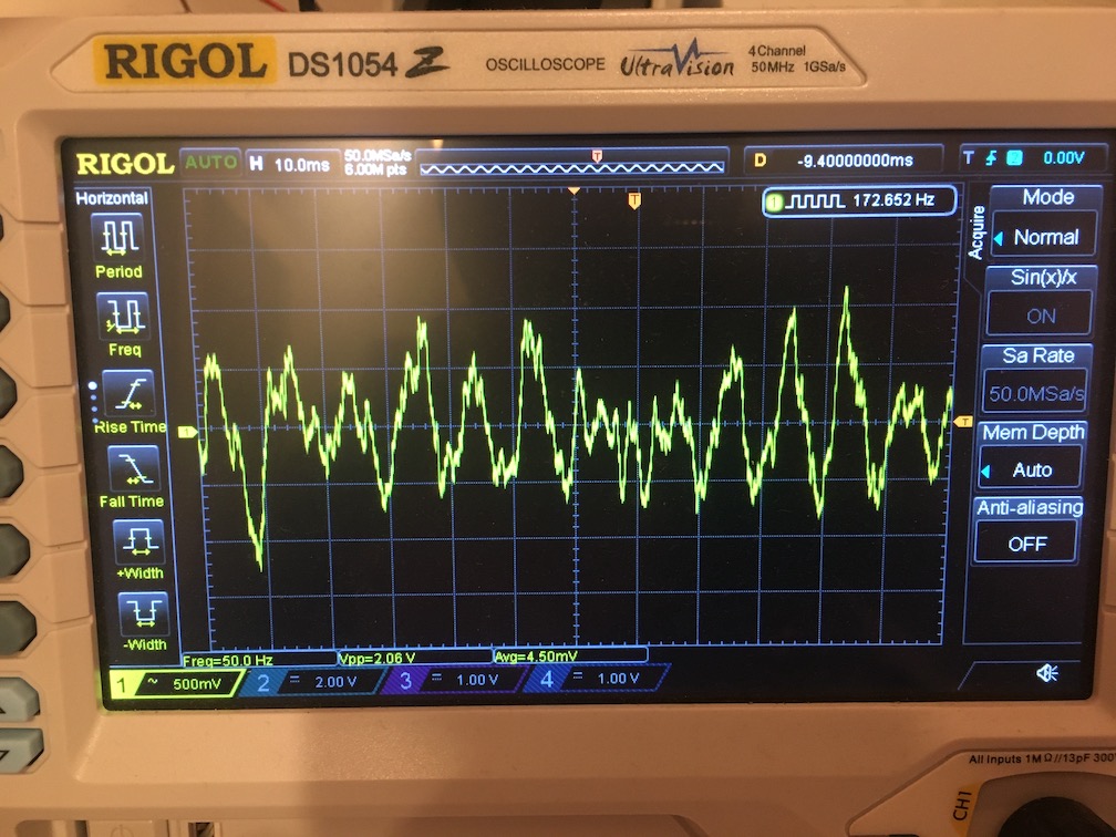
A choppy 2V sine wave, amplified from a 4µV input signal
We see that the 20mV signal becomes 2V, a gain of 100. After both stages, the total gain of a myo3 board is 500,000x, or 114 dB of gain. But that's not impressive if the noise is high — so what is the noise?
Noise measuring setup
I'm connecting the two inputs to the INA, and then grounding them to the center voltage of the power rails.
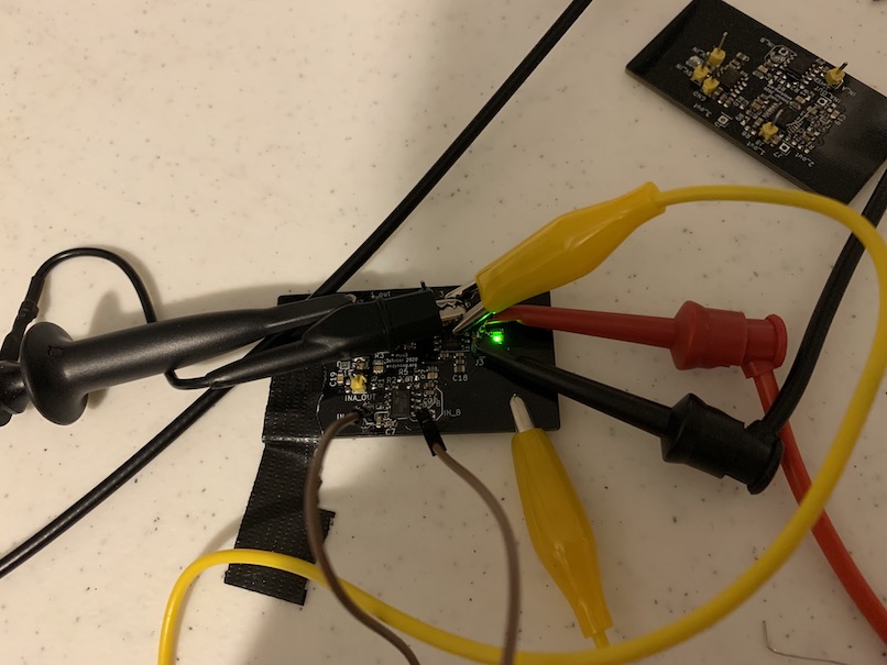
Noise testing setup for myo3
And here's what the output looks like after both stages:
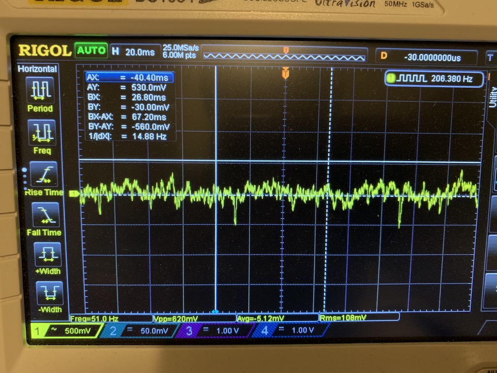
Output signal of the myo3 after shorting its inputs. Peak to peak noise is 620 mV
Looks bad right? Well, let's do the calculation.
After 500,000x gain, the output noise has a peak-to-peak voltage of 600-900mV. 0.62V/500000 = 0.00000124, or 1.24 µV.
The total noise on the inputs is under 2 µV, before any digital filtering or averaging. Wow! And that's across 50kΩ of resistance, meaning its got low current noise AND voltage noise. For reference, that's less than the thermal noise on a 100kΩ resistor at 20C and 1000Hz bandwidth.
I think this circuit definitely achieves my original goal of making a biosensing board that doesn't have awful noise dwarfing the measurements. We'll see how it fares in a real test when my USB isolator arrives.