Bringing up a custom RP2040 board
Published May 21, 2025
Hello, today I'm gonna walk you through putting the RP2040 on a custom PCB and programming it. I'm used to Arduino but chose to use picotools for this — but I'm getting ahead of myself. Target audience is Arduino script kiddies.
The screen that's in your future
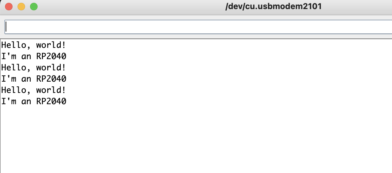
Table of Contents
1. What's this for2. Hardware
2.1 Schematic
2.2 Layout
3. Embedded / Software
3.1 Method 1: download one
3.2 Method 2: Arduino IDE
3.3 Method 3: Build it yourself
4. Warning: I2C/SPI/UART/PWM pins are baked into hardware. PIO isn't, but parallel reads should be adjacent pins
5. Conclusion
What's this for
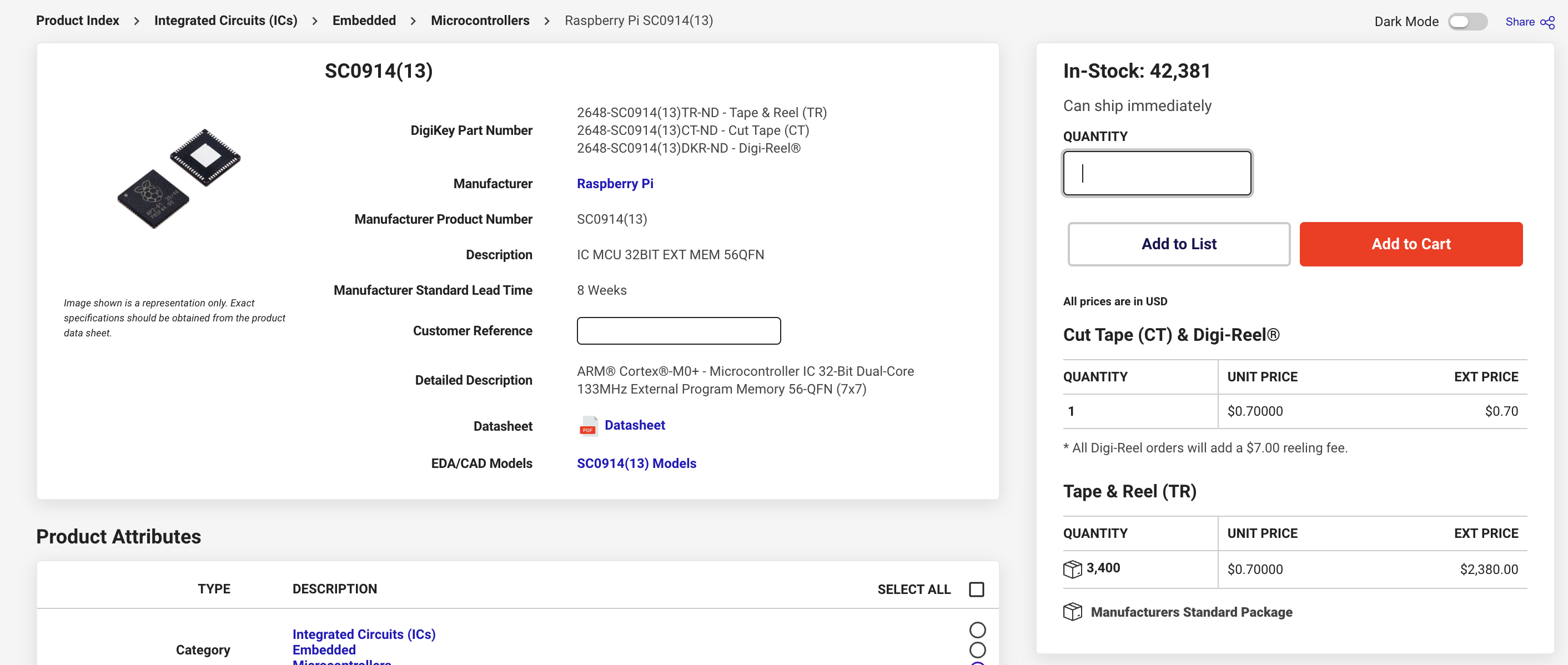
Ok so sometimes you want to make your circuit small, or just well-integrated, and a messy breadboard takes up a lot of space and decreases your investability (Sometimes it increases it, see Orbit's blog for an example). In this situation you want to put the microcontroller on a custom PCB. Then programming gets complicated — the USB datastream from Arduino can't upload directly to most ICs, requiring a translator chip (USB->UART) to convert it, which is another chip to figure out. Or maybe cost is an issue. The RP2040 hits both targets, costing ~70c (as of 2025) and allowing direct USB input for programming.
Hardware
Schematic
First step is the schematic and layout. Most manufacturers publish a minimal set of components needed to run their chip, and RP2040 is no different. The schematic can be found on this blog and I've ported the picture for posterity.
Minimal schematic for RP2040
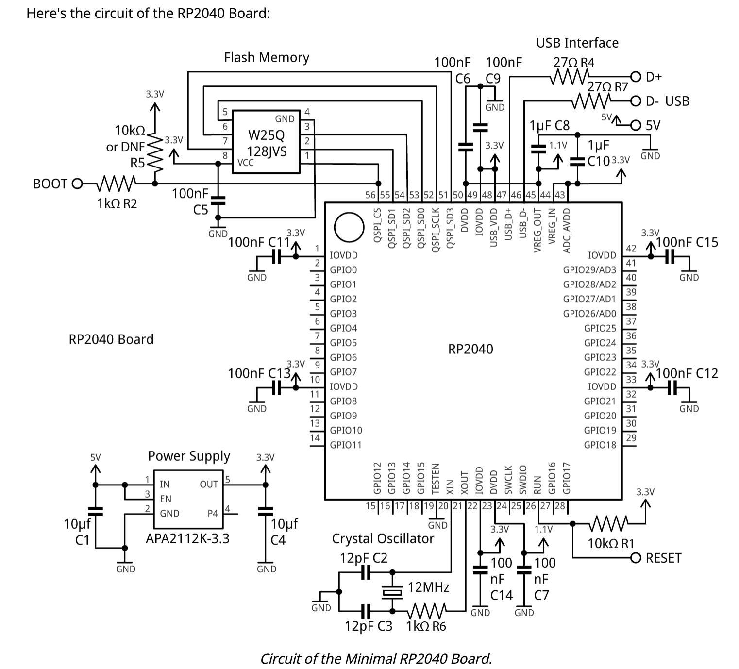
None of the parts are really special. The power converter is needed to change 5V into 3.3V (max VIN is like 3.6V I think?), anad then the D+ and D- lines from the USB which carry the programming require in-line resistors to (I think) incur a voltage drop so they don't break the input pins (5V signals directly might wreck those pins). The flash chip they use is required (no on-chip flash like Arduino or others), but is pretty cheap and stocked by most PCB shops.
You'll want a BOOTSEL button, ask me how I know
This board really is the minimal set, but there's a few more bits I'd add to make your life easier. For example, if BOOT is connected to GND on startup, the RP2040 goes into BOOTSEL mode, which you need in order to program it IF you also want to get debug messages over USB. So you should probably add a pushbutton bridging BOOT and GND. You might also want to do this for the RESET pin. Otherwise you'll have to do this with a paperclip or a pen spring.
I'd also add an LED + resistor from the 3.3V supply, just so we can tell when the thing is on or not, and then another LED + resistor wired to an unused GPIO so we can use a Blink sketch to check if our uploads are working.
Layout
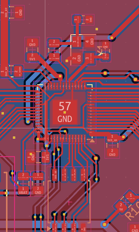
There's a lot of recommendations on the datasheet for where to place everything, but really it comes down to priority. IMO everything should stay on the same plane as long as possible. High-speed stuff (crystal) needs to be quite close, and decoupling caps shouldn't be much further. For the flash and other sensors, proximity won't matter much.
Embedded / Software
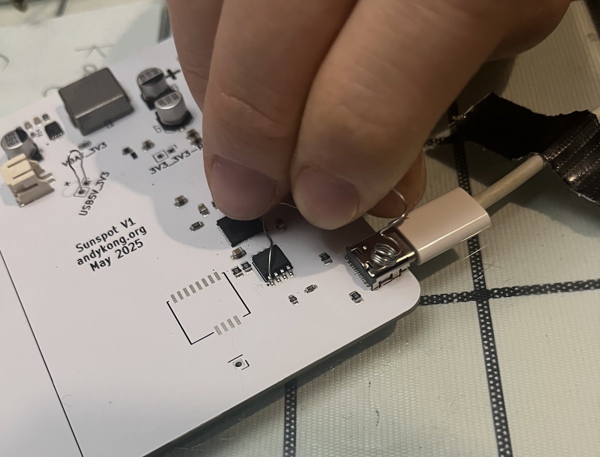
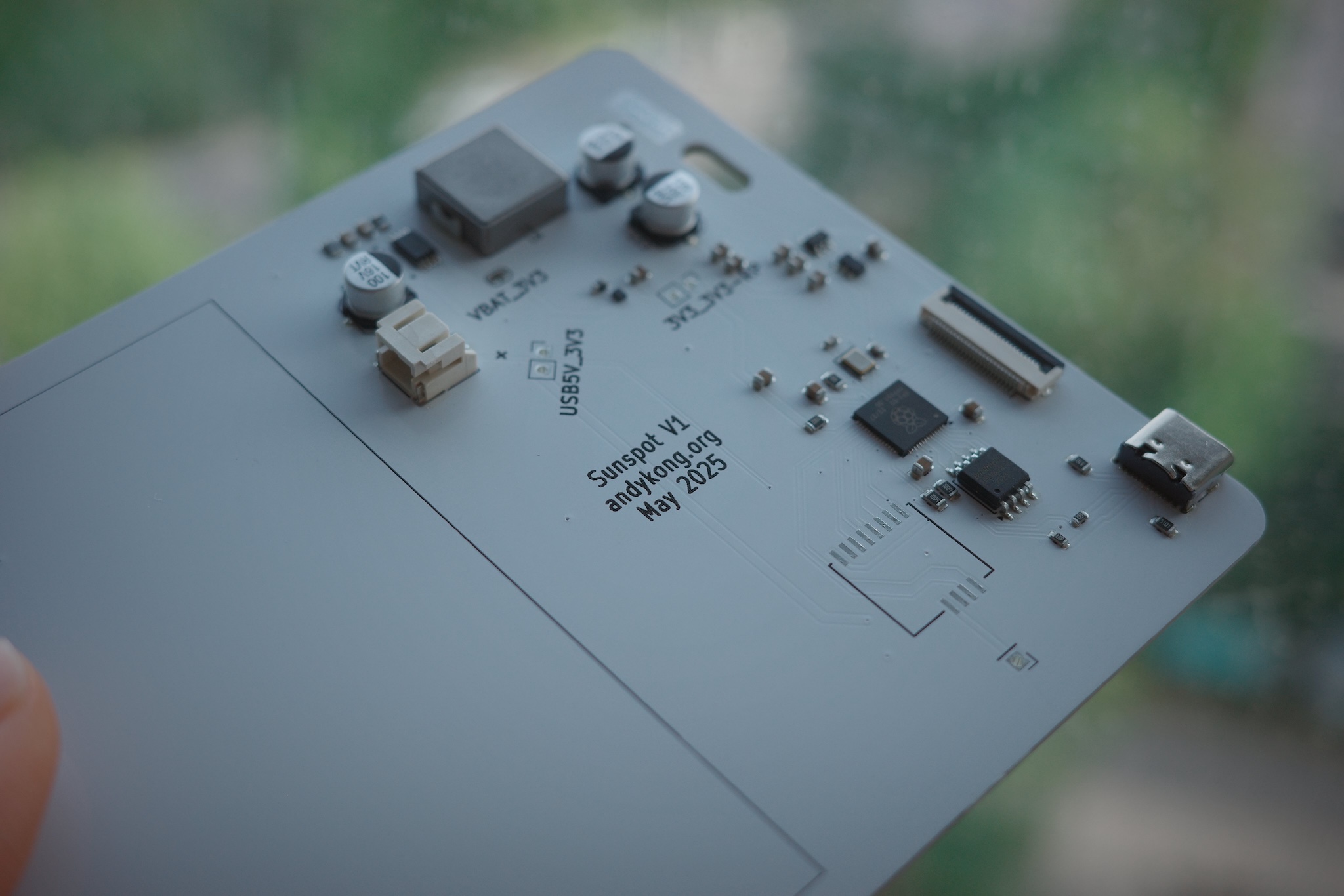
My board
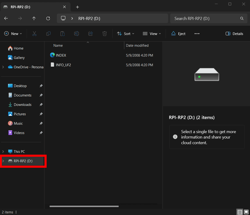
When you first plug it in, the RP2040 will not show up as a progammable device port in the Arduino IDE, instead your computer will beep and tell you about the new USB flash drive you just plugged in. The USB device that shows up is the RP2040 in BOOTSEL mode, which by default exposes itself as a USB stick which you can program via drag n' drop with a .uf2 file. The IC saves the program to flash and unplugs itself (in software). After you upload a valid uf2, the RP2040 stops showing up as a USB mass storage device, and if you want to upload another UF2 (instead of through the IDE) you'll need to power cycle it while holding down the BOOTSEL button.
If it doesn't show up as a USB device, that sucks (you may have forgotten to route the power (I did this), just probe stuff and look at the schematic until it makes sense.
from [here](https://th.cytron.io/tutorial/setting-up-maker-uno-rp2040-arduino)
Now you might be thinking to yourself, where do I get a .uf2 file? Ok so three ways I know of.
Method 1: download one
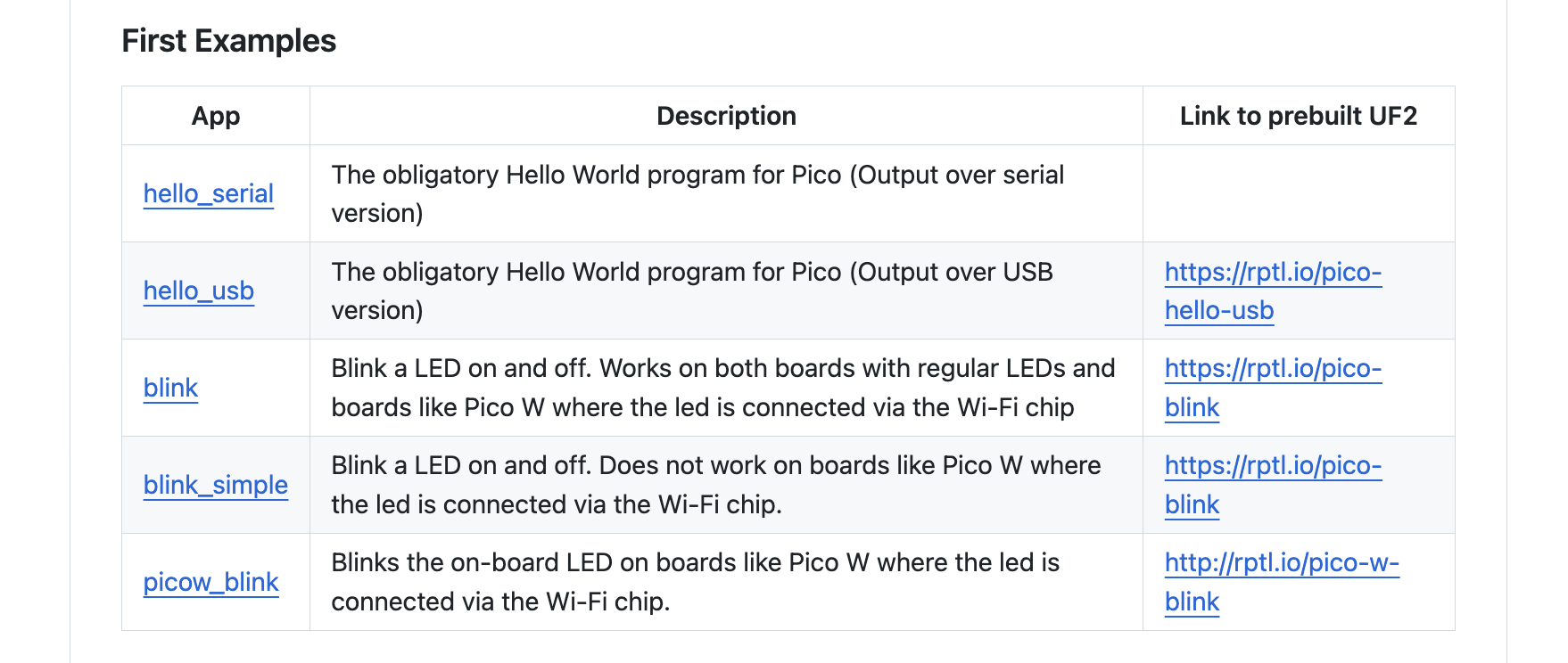
There's some basic "check functionality" sketches in the raspberrypi/pico-examples github repo which you can download and then upload directly. You can't edit these, but they let you check that the IC is soldered properly.
Method 2: Arduino IDE
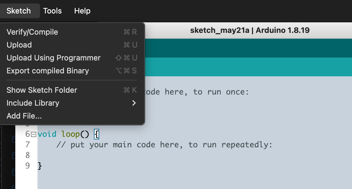
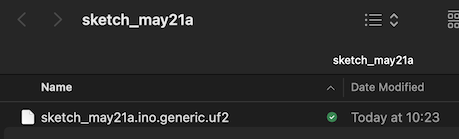
Arduino IDE can actually generate uf2 files, you just have to go to Sketch and hit "Export compiled Binary". This will compile the program for the selected target board (Make sure you're on Tools -> Board -> Raspberry Pi RP2040 Boards -> Generic RP2040) and saves it to the sketch folder. Just to to the sketch folder and drag+drop your uf2.
Export compiled Binary option exports as uf2
Method 3: Build it yourself
Here I must admit I never really learned embedded in school, so my understanding of this is patchy. Basically you write your program in .c and .h files and compile them using Cmake + make. You 'include' libraries by telling CMakeLists.txt to link them, which CMake will pull from the pico-sdk (you need to tell CMake where this is too), at which point your programs will know where they are. Then all this gets compiled together into a binary .elf or .bin or .uf2 file by make. So the steps are, roughly:
-
Install + cmake + build the pico-sdk, reference it in your
.bash_rcor whatever -
Make .c and .h files however you want, including the libraries you need to use at the top (same format as Arduino,
#include <stdio.h>) -
Add your used libraries into the
CMakeLists.txtfile undertarget_link_libraries(${PROJECT_NAME} -
Make a
build/directory, go into it, runcmake ..and thenmake, there should be no errors, and if there are, you should fix them. -
To program the RP2040, you can either 1) upload the output
.uf2file to the RP2040 mass storage device by drag n' drop or 2) to flash from the command line, install picotool, make sure the board is visible by runningpicotool info, then flashing usingpicotool load <blah.elf>if your RP2040 is in BOOTSEL (still a USB mass storage device) orpicotool load <blah.elf> -fif the RP2040 isn't showing up as a USB device anymore.
There's a minimal example for how to do all this on Github at oguzbilgic/pico-minimal-build, and ChatGPT is pretty helpful for debugging. I learned a lot from figuring out this part, but I needed to do this to run someone else's example program — it might not be worth if you don't have this constraint and will only do simple stuff.
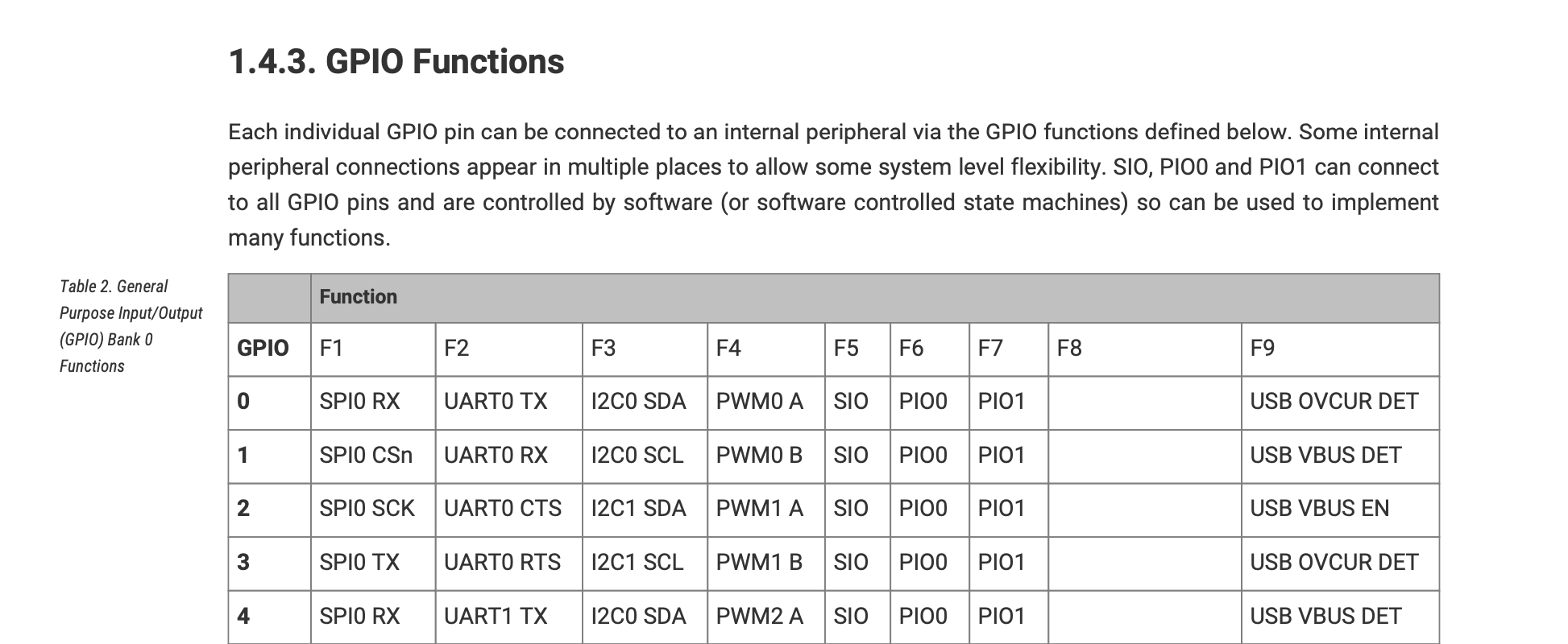
Warning: I2C/SPI/UART/PWM pins are baked into hardware. PIO isn't, but parallel reads should be adjacent pins
If you want to use the native I2C/SPI/UART functions, you should know that certain pins are destined to be SCL/SDA and not both. And if you use PWM, make sure your PWM outputs don't share a PWM object + channel (e.g. if two pins are PWM0 A, you will only be able to PWM from one at a time). Just check the datasheet, it'll save you a rev.
PIO is out of the scope of this post, but is mappable to any pin. However, if you need to do a parallel read of 8 channels (like for a camera MIPI), the channels should be arranged in-order going to sequential in-order GPIOs.
Conclusion
Ok, relatively painless. Simple schematic, layout, and pretty straightforward embedded. RP2040 is a chip is nice, not particularly low-power, but lots of GPIO, communication channels, ADCs, and it's really cheap. But I'll let you know what I think in a few weeks once I've used it more.
Cya!