Supercapacitor To Lithium Battery Converter
Published February 14, 2022
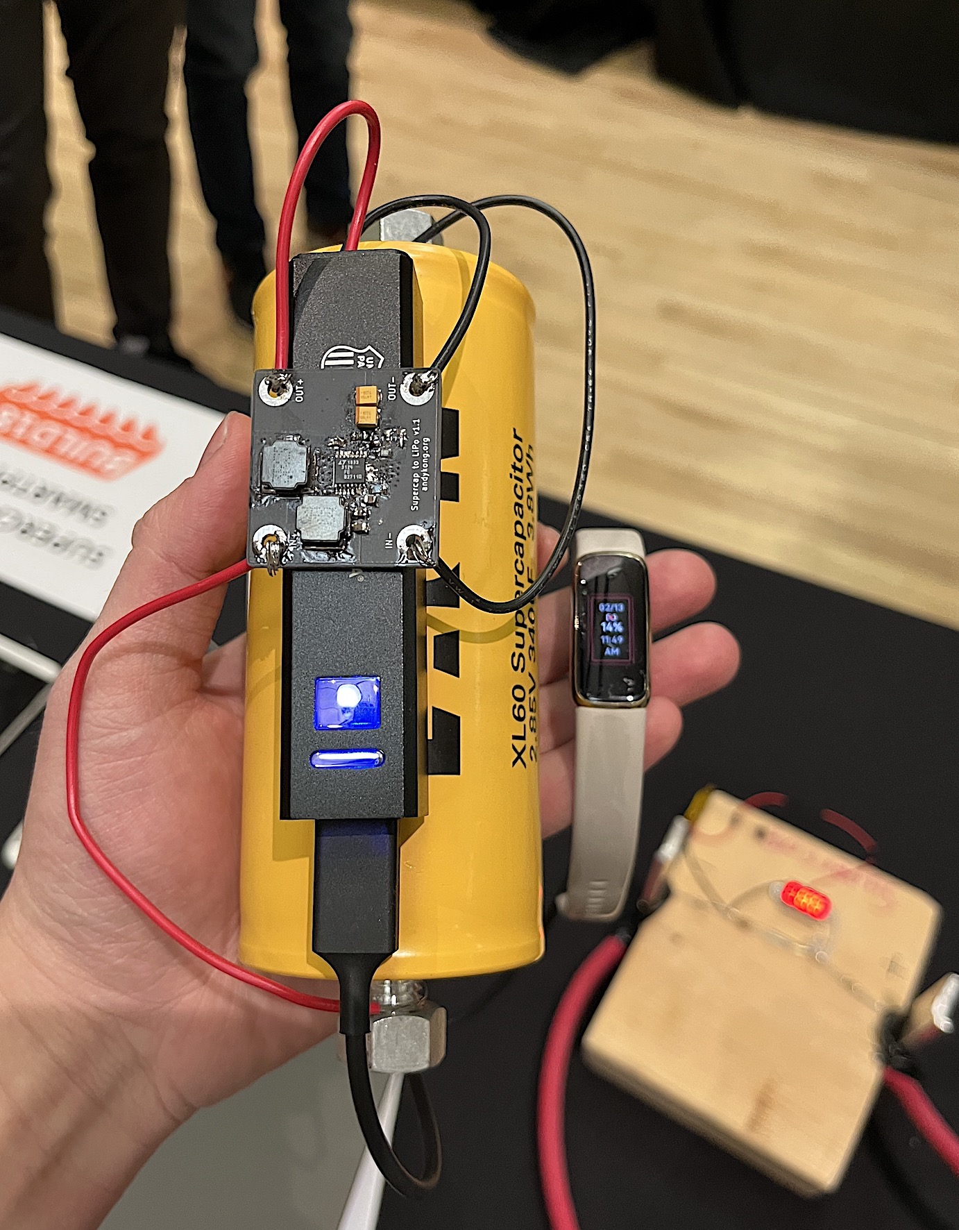
This past weekend, I attended my last Build18 as an undergrad. Build18 is a hardware hackathon at CMU which gives student teams a $300 budget to buy any parts they want, to build any project they'd like. This time around, I decided to convert a smartphone to use a supercapacitor instead of its lithium battery. The benefit of a supercapacitor is that it's easier to hold, and that it can charge around 100x faster than a lithium battery. The only downside is that it's massive.
Size of the supercap, here charging my FitBit
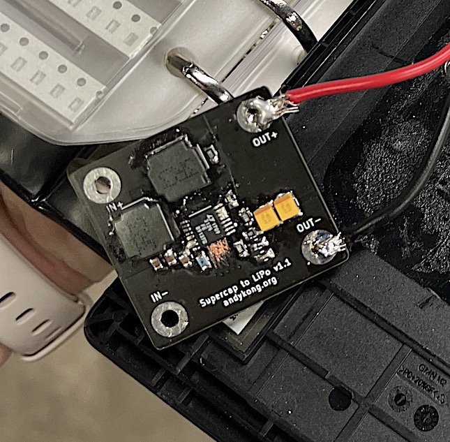
To replace the lipo, I needed to convert supercapacitor voltages (0-3V) to lithium battery voltages (3.7-4.2V). The most common boost/buck-boost circuits online start working at 3V, which is just out of reach of all supercaps, so I made custom boost converter board based on an application note from the LTC3124. This post tests a few metrics of this board.
Most consumer electronics use lipos, and by making this board, I hope to make any future device supercap conversions easy to do. The boost converter circuit keeps working down to 0.5V, and only kicks in around 1.7V.
Supercap board alone
Testing Metrics
The metrics I'm interested in are maximum continuous current output and efficiency.
The problem with powering a former-LiPo device with a supercap is that the boost converter bottlenecks the current. Even if the supercap can handle a device spike of 2 amps, the boost converter may not be able to, sending the voltage crashing. The maximum continuous current output lets me know which devices can use this converter board.
The supercap's low energy density also means that the cap alone is only 2/3 or so of the total energy in a smartphone battery, and is only made worse by the inefficiency in the boost converter. The efficiency lets us get a measurement of how much current we can expect to use from the supercap.
Setup
Setup for testing the board
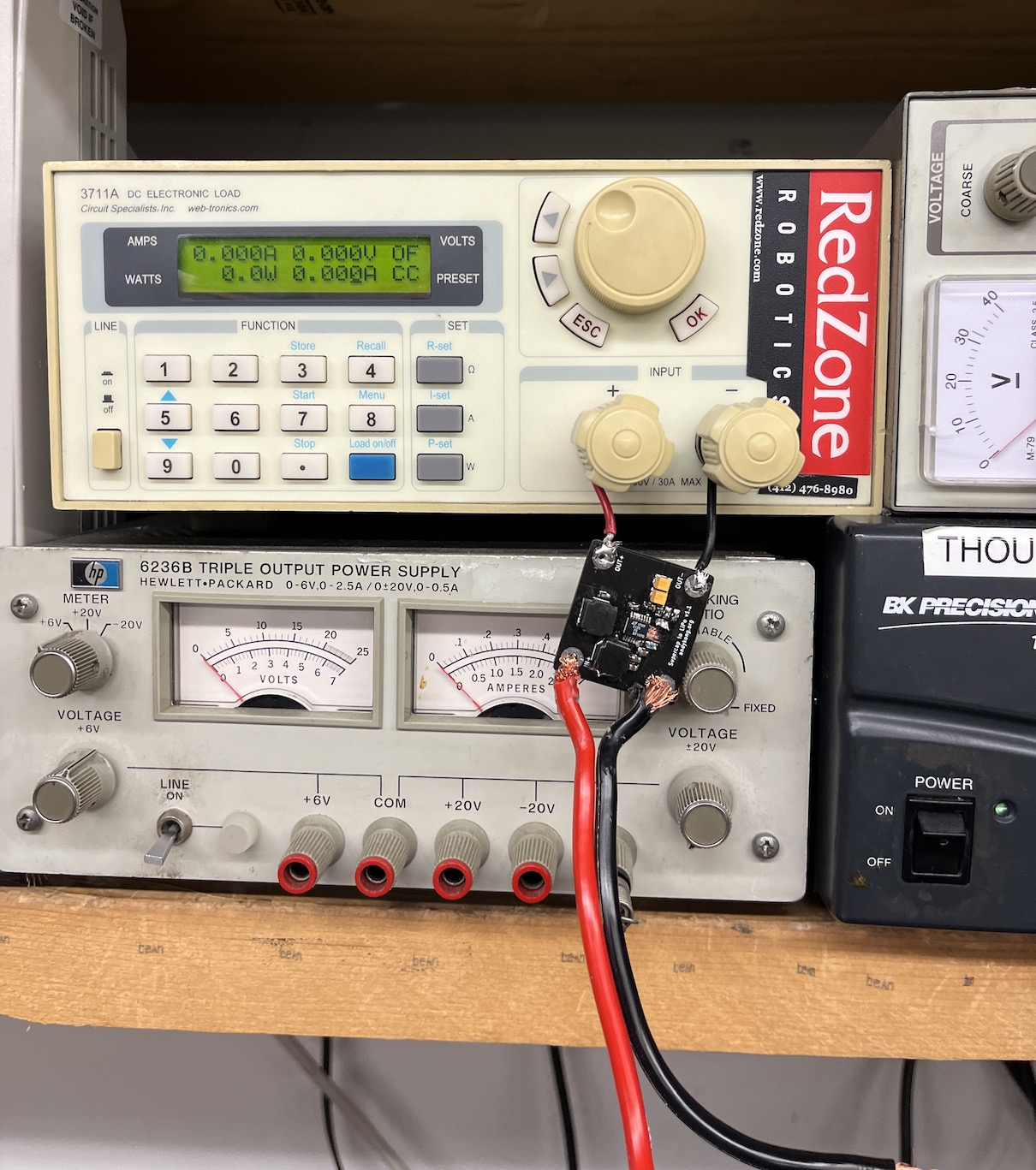
I used a DC electronic load and a 3V/3A power supply for testing, and this board is set to output 4V. Here's the data:
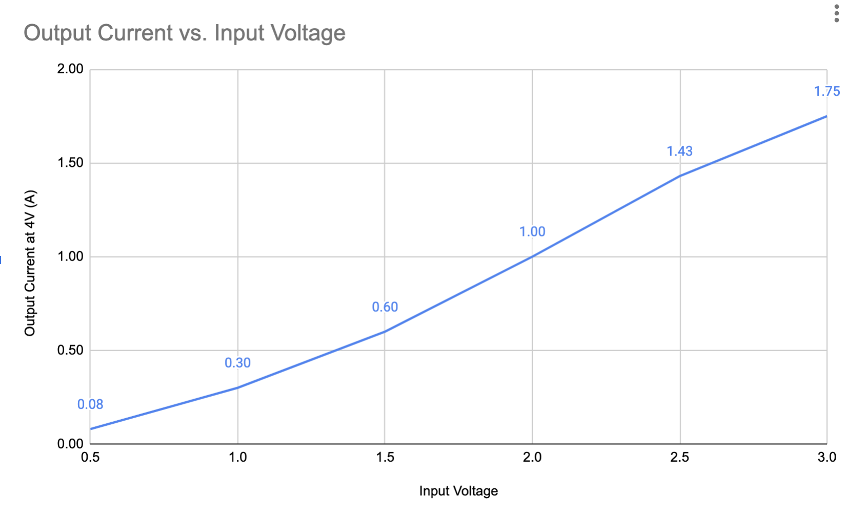
Maximum continuous current out at 4V output
Efficiency at 4V for various input voltages
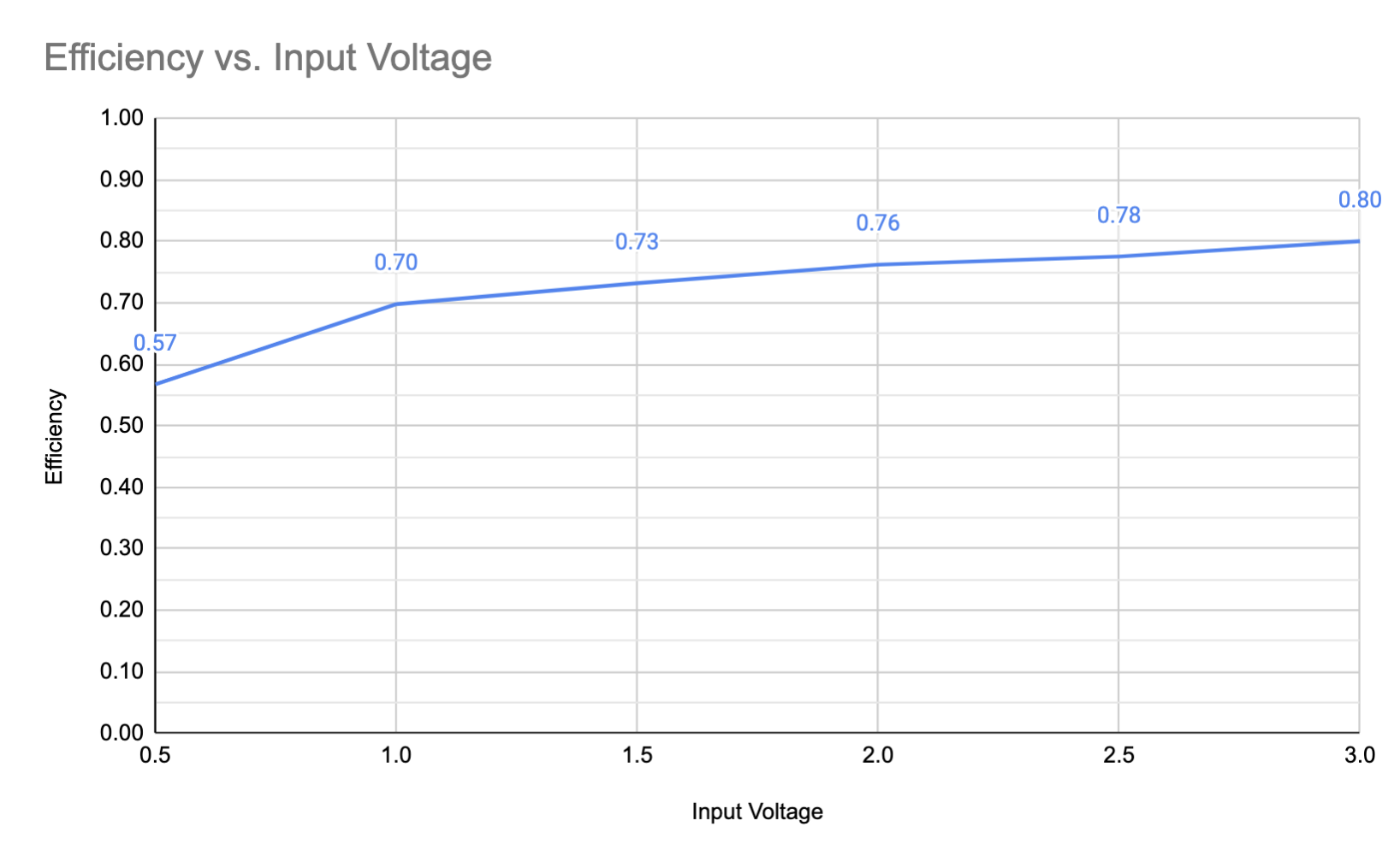
Considering the cap's total power scales with $V^2$, we are well above 70% efficiency for 90% of the energy of the cap. Also, the 0.6A current output at 1.5V is enough to power a smartphone, since most of the time they draw 200-500mA (except on startup).
Comparison
Crudely, the efficiency cuts down the capacity by 75%, and it only works (for smartphones, depends on current load) down to around 1.25V. At peak, the supercap is 2.85V, so we can use 1.25^2/2.85^2 = 80.7% of the power in the cap. This means when we calculate the equivalent lipo capacity of a supercap, we need to downrate it to 60% of total capacity. Ouch!
Could another boost converter be better? Well, the 80% downgrade is inherent to the supercapacitor at certain current output needs, and I don't think many boards can boost and output >0.5A below 1.25V. I did see one more TI part which was out of stock for two years though, and it can do a bit higher current. The 75% efficiency can be better, but not at high current draws, and is capped at 90%. A realistically perfect converter would yield around 90%x90% = 80% of the supercapacitor power, which is a lot more than this board's 60%. However, this converter board works pretty well, and it's not like supercapacitors don't already have a supply issue already.
Conclusion
One day I will get my hands on that TPS chip, but until next time, cya!