Touch Reactive LEDs
Published January 29, 2021
Hi! Today I’m going to go over a small Arduino project I made using LEDs and the FastTouch library.
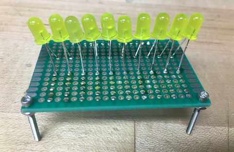
It's a row of LEDs mounted in protoboard that lights up when you touch the front lead. Multiple can be touched at one time. The only interesting part of the code is allowing each pin to both detect touch and power the LED. Here's why.
Made a little row of LEDs touch-sensitive. Tracks with your finger really fast! pic.twitter.com/C6R0Aa9zEK
— Andy Kong (@redlightguru) January 24, 2021
How FastTouch detects human touch
So the way the FastTouch library works is by detecting the capacitance of the human body, which is a few hundred picofarad. When assigned to a pin, it configures the pin it's reading as INPUT_PULLUP, which means it's held at 5V by a ~10k internal resistor. Then it changes the pin to OUTPUT and writes the pin as LOW, and counts how long that pin takes to hit 0V. If there's a human touching the pin, we're holding some of the charge from the 5V on the pin, so it takes longer to discharge to 0V. If we're not touching it, then it should discharge almost immediately.
This works best if the human is touching the ground of the Arduino with their other hand, but also works without that because we are capacitively coupled to our environment, and the ground of the Arduino through the air (something I don't understand well enough to explain here).
Top, unlit LEDs
Problem
Because the library counts how long each pin takes to discharge, if we just wired an LED+resistor in series from the pin output to ground, it would discharge immediately through the LED and read no human touch. If I had used one pin for the touch and one pin for the LED, I'd only be able to do 6 LEDs because the Arduino only has around 12 usable pins. So what did we do?
Solution
Instead of wiring the LED to ground, each one is wired to a pin that is held HIGH when we check the touch, then brought LOW (ground) when we light the LED. Because the LED prevents backwards current flow, it's an open circuit when checking touch, then allows forward current to light it up when indicating touch detection. Boom! 2x reduction in pins.
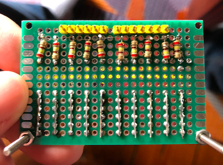
Picture of the underside of the board. Alternating resistors
Construction
This took me like two hours to solder and put together, mainly because A) the LEDs had to be in front of the finger pads for visibility, but the pins behind the LEDs had to connect to the finger pads in front, and B) I wanted it to look nice.
That's all for now, take care.