Body Channel Communication
Identifying users by their touch alone
Timespan: April 2021 - May 2021
Published: 2021-10-08
Inspiration
While walking down Craig Street one day, I was struck by inspiration! All of a sudden, I remembered that human skin conducted electricty, which meant it could also conduct signals! I thought immediately of 3-4 applications: touching your house's doorknob and having it unlock after recognizing you, turning on your car by touching your steering wheel without ever needing your keys, etc. The possibilities are all variations on a theme, but it's a damn good theme.
I immediately went to Roboclub and began building a simple version. Very quickly I learned that it is difficult to send signals without a ground, but I had a prototype! I excitedly showed my friend, and he had some bubble-bursting news. As it often turns out, I am not the only one to think of this.
People like Mr. Alanson Sample have beaten me to it in 2018, and I found papers about this idea as early as 2010. Formally, the idea of using the body as a wire is called Body Channel Communication (BCC) or Human Body Communication (HBC). They even made these great figures describing it!

Nice Disney Research mock-ups
After being disappointed in myself for not being born 3 years earlier and thinking of it, I sort of gave up on the topic. Not until my Sensing class mentioned a 2-month class project did I think of BCC again, and I proposed it on our big spreadsheet. Two of my classmates were interested, and we gave it a good crack. We made a shared ground version originally, but then we also got a wearable, wireless version working!
The rest of this article will be a pruned version of my group's final writeup without the redundant bits.
Body Channel Communication Introduction
Due to the human body’s high ionic concentration, electrical conductivity is fair across the skin and through the body. Because of this, any electrical waveform touching your body will also propagate through to anything you touch. We can harness this effect to give any wearable or device the ability to identify you and the objects you contact. For example, your smart watch could detect when you touch your smart doorknob, then authenticate and unlock it for you without needing a key or code entry.
Our project aims to Implement a robust body channel communication system using wrist-worn microcontrollers as the receiver and various instrumented objects as transmitters. Specifically, we intend to implement an entry security/authentication system in which a “smartwatch” transmits a unique ID through our skin and is received by a microcontroller hooked up to a doorknob.
Nice Disney Research mock-ups showing what could be possible
BCC opens up a wide range of possibilities for a user to interface with any device with a basic microcontroller. This allows information to be transmitted through a user’s touch, without adding an extra step of unlocking, identifying, or scanning. Touch input also enables the whole body to be used for input, not just the hands. This has obvious advantages over RFID. One application is unlocking a smart door: when an authorized user touches any part of their body to the door, their watch transmits an authenticated ID from their smartwatch (TX) to the door (RX) and unlocks it.
One of the benefits of BCC is that it can be implemented on basic electronic hardware, allowing it to extend the usefulness of smartwatches. However, using the body to carry signals degrades the quality of the transmission, slowing down the bitrate or compromising the reliability. The signals also must transmit bits without using a shared ground potential. To overcome both of these, we can use a high frequency carrier wave to carry our bits.
Implementation Details
Due to time constraints and initial problems with getting unshared ground working, we prototyped using both shared and unshared ground. Both involved complicated signal processing, with shared ground requiring more digital smoothing and unshared ground requiring more analog processing.
Sending and Receiving Digital IDs (Shared Ground)
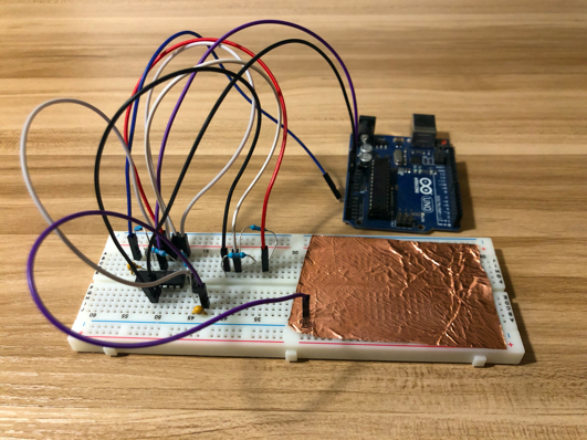
The shared ground BCC circuits are fairly simple: the transmitter consists of a signal pin (digital out) and the receiver consists of a receiving pin (analog in) tied to ground with a resistor (around 360 kΩ - 1MΩ).
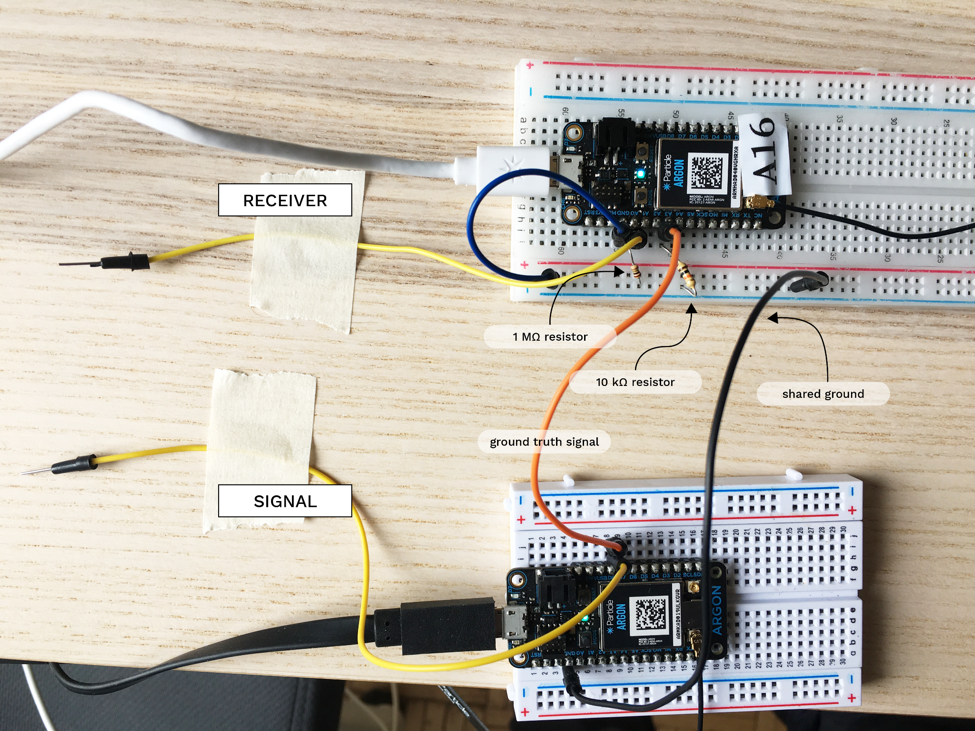
BCC shared ground setup
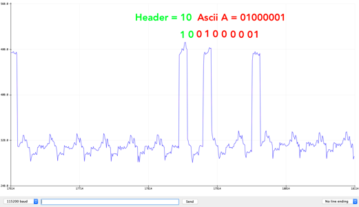
We decided to use byte-sized IDs (single characters) as a proof of concept to keep things simple. On the transmission side, bits are masked out one at a time and sent as a square wave with a period of 10ms. As such, if the ID were to be ‘M’, the transmitter would send a square wave with M’s ASCII value: 10101101, as seen below.
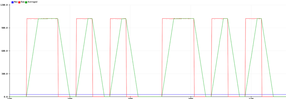
BCC shared ground, the signal we're sending is in green
On the receiving end, the main challenge was dealing with the noisy signal. As can be seen in the picture below, the digital signal (shown in red) through our bodies is received with a lot of noise, so we use a fixed-size queue to compute a running mean of the signal and use that as our input (shown in green).
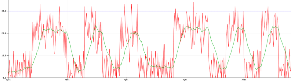
BCC shared ground, the signal we're receiving is in red, and smoothed in green
To read the ID from this signal, we wait for the averaged signal to first change value (to synchronize with the transmitter’s clock ticks) and then read values after each period. Each value is then bit shifted into a character so that after at most 7 periods, it should equal the transmitted character.
Sending and Receiving Digital IDs (Unshared Ground)
Sending messages between devices usually takes place in the digital domain, and needs at least two wires: One for the ground, and one of the signal. The ground defines the 0 and 1 that both devices share; without it, there is no HIGH or LOW signal, there are just two floating voltages.
The difficult part of sending signals over the body is that the body is one wire, and without a shared ground it is impossible to transmit DC HIGH and LOW signals directly across it. The body must be treated like an antenna instead, with the signal of interest encoded onto a high frequency carrier wave which needs to be decoded on the other side.
We present an overview of our groundless system. More details can be found here.
Transmitter circuit
Using the Arduino’s clock as the carrier, we modulated our bits as the output using a transistor and a digital pin. When the modulation is HIGH, the clock is grounded and the output is nothing. When the modulation is LOW, the output is the clock.
![]()
Wrist-worn transmitter, with a conductive band and a transistor acting as a signal modulator
![]()
Transmitter circuit
Receiver circuit
The receiver is a passive RC filter at 159 Hz followed by a gain stage set at 300 using a general-purpose op amp. This output is then fed into the Arduino ADC.
Receiver setup
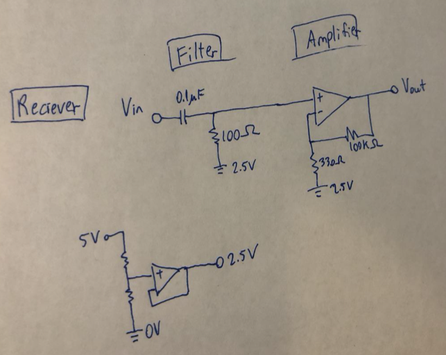
Receiver circuit
Results
Our groundless body channel communication system can transmit at a bitrate up to 1kHz with minimal signal degradation due to analog filtering and amplification. Here's what the transmitter is emitting:
![]()
Transmitted signal
And on the other wise, here is what the receiver sees post-filter + amplification. Transmitted bits are obvious.
Received signal
Demos and Prototyping Process
We implemented a couple of demos to showcase potential applications of our BCC system.
Smart door lock
As described in the introduction, our first demo shows the potential of BCC in authentication, for example for smart locks programmed to grant access to a set of users. A wearable device making contact with the user's skin transmits their unique ID (a simple implementation of this in our demo: character 'A' or 'M'). When the user touches the door knob, the smart lock receiver parses the user ID and grants access accordingly. Because of the time constraints and challenges we ran into with unshared ground circuits, we implemented the demo with shared ground.
We designed an enclosure with a wrist strap to hold one transmitting microcontroller on the user's arm. A wire runs from the transmitter (output) pin to the surface of the enclosure that touches the user's skin. In a more refined prototype, the enclosure could be inset with a conductive material that connects to the transmitter pin. This would also provide a larger surface area for better coupling.
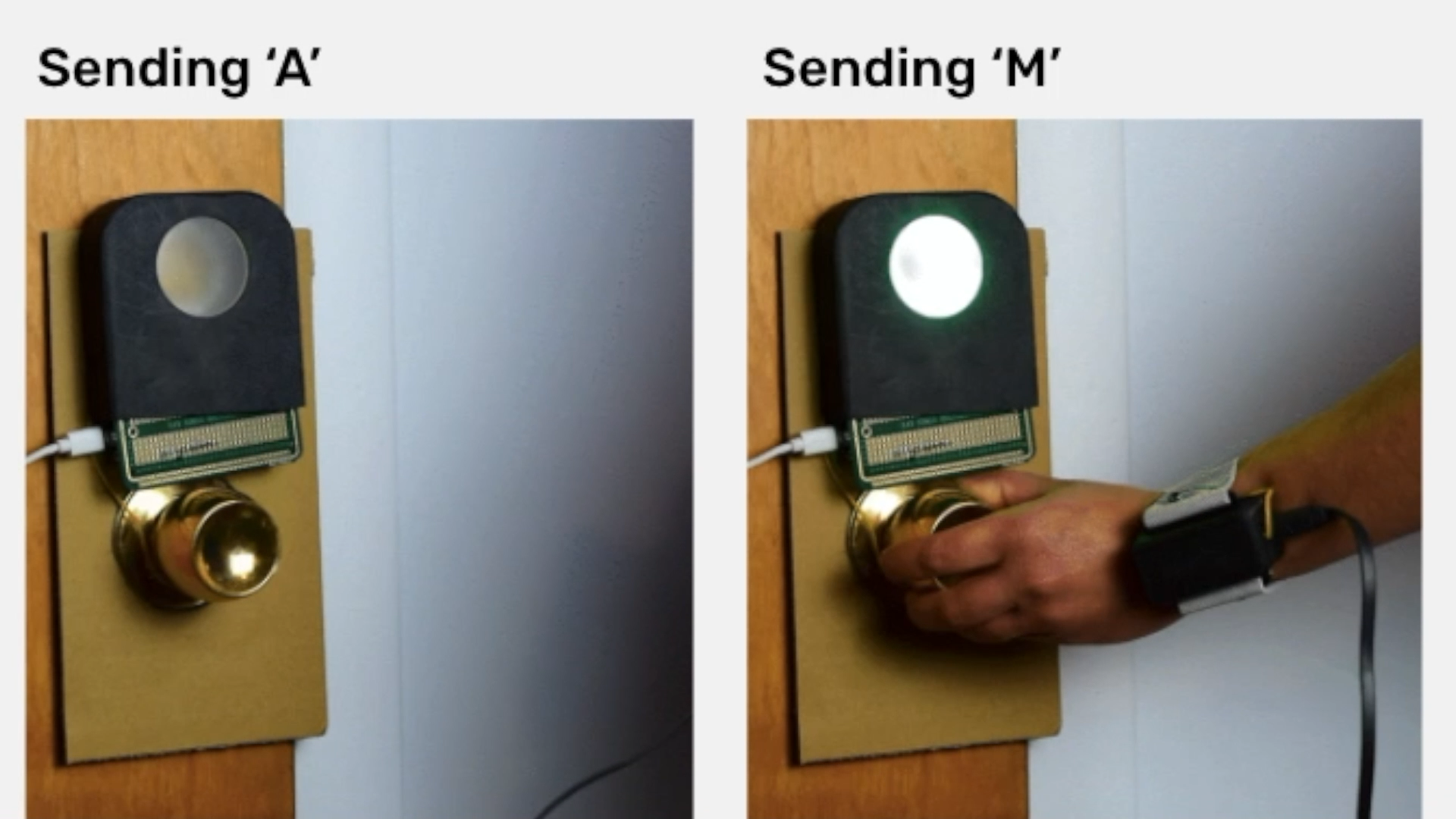
Another enclosure is mounted on the door to hold the receiving microcontroller. In addition to the simple shared ground circuit with the receiving (input) pin and resistor to ground, we added an LED (Neopixel) to indicate whether access is granted (green light) or denied (red light).
The enclosures were designed to be 3D-printed on an SLA printer. Because of print failures and time constraints they were ultimately printed on an FDM printer, resulting in some minor tolerance/resolution issues.
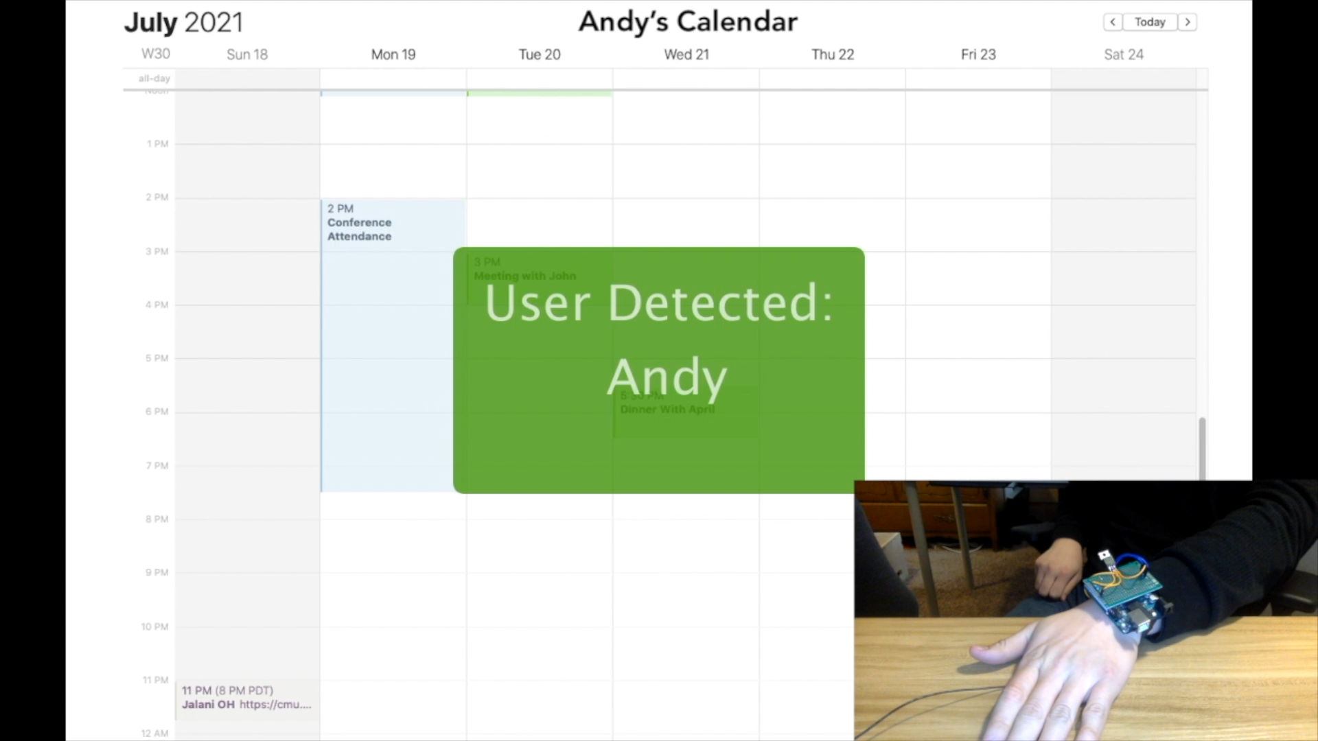
User-Aware Calendar
Our second demo shows the possibilities for personalization with BCC using a wearable device on each user’s wrist, also by transmitting user IDs through touch. In the demo, a calendar display updates to show the personal calendar of the user who has just touched the receiver pad. When user A touches the receiver pad, their ID ‘A’ is parsed by the receiver microcontroller, which communicates over Serial with a Processing script that updates the display to show their personal calendar.