Myo2
Making my own ultra-sensitive EMG sensors for measuring unnoticeable muscle movement
Timespan: July 2020 - now
Published: 2020-10-23
Here it is! My own EMG sensor board, capable of amplifying 50uV muscle signals into ~1V outputs without getting drowned out by electromagnetic interference or noise. Total gain is around 30,000x.
Myo2 muscle tensing test gif. Two hard contractions followed by a lighter, discreet contraction.
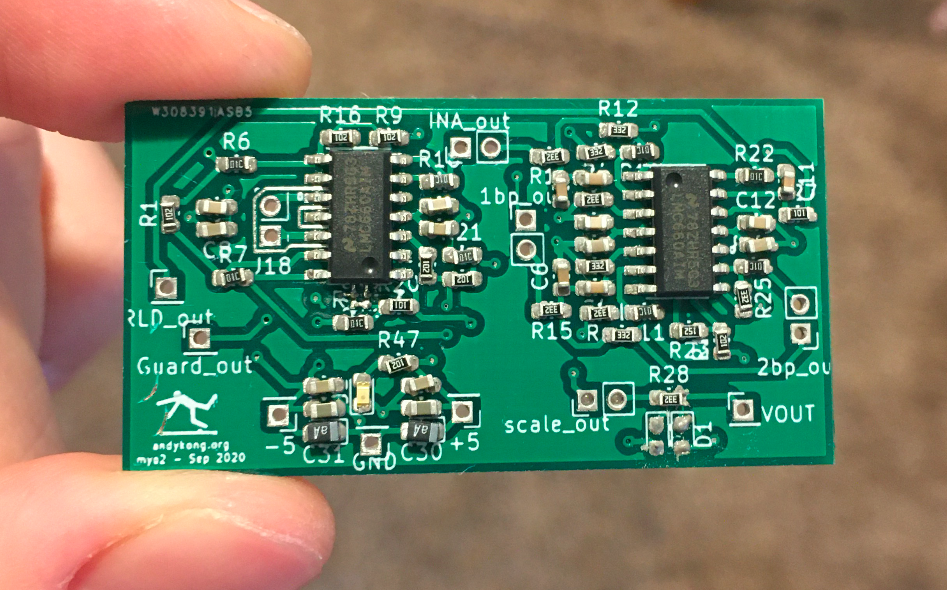
Myo2 fully populated board, with level-shifting, right leg drive, and driven ground (and a guard ring on the inputs!)
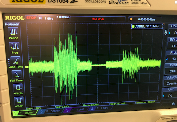
Muscle contraction test. The two clusters of activity are different electrode positions.
Motivation
Here's a fun question: what's the difference between a muscle-computer interface that can detect contractions before they happen, and a brain-computer interface? To an outside observer, I'd say not much.
Anyone can do normal EMG: the Myoware sensor for that is for sale on Sparkfun. But what if you could detect muscle movement before it happens? I knew this was feasible because of a guest lecture I saw at CMU. Professor Douglas Weber could detect muscle activations around 10 uV, which weren't strong enough to recruit muscle fibers, but were strong enough to detect using good electronics.
CTRL-Labs also reportedly could do this: they claimed in a few articles that their armband could detect intent to move before the movement visibly occurred. This was very exciting to me, since I wanted to see if their tech actually worked like they said. Then they got bought by Facebook, so I'll never get to see it until it's released in a product in 5 years :(.
This led me to design and build my own EMG sensors.
Specifications
When a muscle tenses, the coordinated opening of the ion channels in the fibers creates an electrical signal within the muscle that propogates outwards to the skin. This creates a very small surface signal, on the order of 1 millivolt.
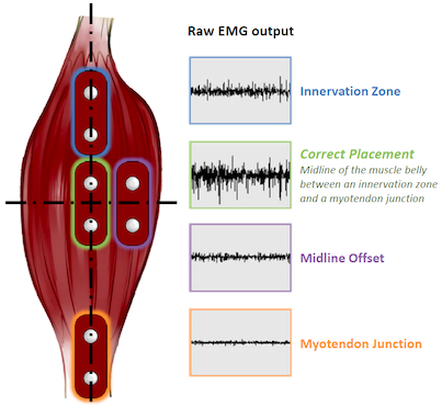
To perform EMG, all you have to do is measure this voltage from the middle of the muscle belly to one end of the muscle. From an electronics standpoint, EMG is a high-noise, high-impedance voltage measurement problem.
Since I wanted to measure nonvisible muscle signals as well as visible ones, my board would need to be ultra-low noise, with a lot of gain stages. Following Douglas Weber's research, the signal I was looking for was on the order of 1-8 microvolts, more than 1000x smaller than the ordinary EMG signal. In addition, since the body acts as an antenna for electromagnetic interference, I'd need amazingly sharp filters to cut out much of the noise before I amplified it so high.
I wanted to turn a 1uV signal into a 100mV signal, a gain of 100,000x! For reference, a 100kOhm resistor alone has 1.3uV of thermal noise, which would ruin our noise floor. This makes my problem much more difficult.
Board Design
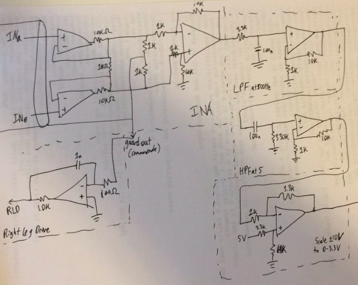
Myo2 caricature of the final schematic. I drew this up for a friend to help me debug, but made errors that make it not feasible if constructed exactly like it's drawn.
The board looks something like this image, but is not this schematic exactly. Roughly, I construct an instrumentation amplifier from 3 ultra-low current noise op-amps to turn the differential signal into a single-ended one, then apply a combination of low-pass, high-pass, and band-pass filtering stages that each have gain to this signal. The output theoretically has 90,000x gain, and around 100 mV of noise.
From the middle of the instrumentation amplifier (representing the common-mode voltage), I generate a driven right leg that is connected back to the user (to reduce common mode noise from the body) and a low-impedance driven guard (to power the guard ring and cable guard for the inputs). This helps with the noise levels on the inputs.
Finally, the output is scaled from ±5V to 0-3.3V, so that I can use a Teensy 4.0 microcontroller to digitize and save the signal onto my computer.
Testing
Tests were initially done with a signal generator as the input. I made a simple voltage divider that would take a signal and divide it by 1000, then feed it into the two inputs of a myo2 board. Then I fed it a 10 mV peak-peak sine wave, and increased the amplitude until the output was visible on the oscilloscope. Around 50 uV the signal was visible; then around 100 uV the signal was very obvious.
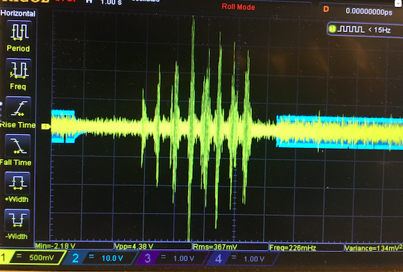
Oscilloscope output of a muscle contraction. The yellow is the muscle signal, the blue is the right leg drive (RLD). When I connect the RLD pin to my body, the output noise on the yellow channel goes down by about 10%
Output gain was not as high as I had hoped due to some imperfections in the filter amplifiers I chose. However, the output signal's noise was almost exactly what was predicted by the op amp's voltage and current noises after undergoing 10,000x gain. So I ran into a limitation in my parts selection, and not my implementation. It always feels good to figure out a problem is in your hardware and not the way you set it up.
Interested in making one?
Email me (check my CV)! I can send all schematics and talk more about my design decisions, just don't want to write it all up.