Body Channel Communication Tutorial Pt. 3
Published May 15, 2021
Hello! I have successfully implemented BCC, transmitting signals across the human body through touch alone. With the help of Sam, anything is possible. In this post I'll show you how it works, and some neat applications.
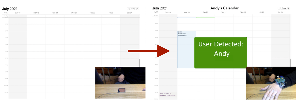
Here's a demo showing a reactive calendar. When a user touches the pad, their smart watch transmits their encoded ID to the computer. When decoded, the computer knows who is touching it, and can show that user's calendar.
Calendar that detects user identity through their touch
Recap of what doesn't work
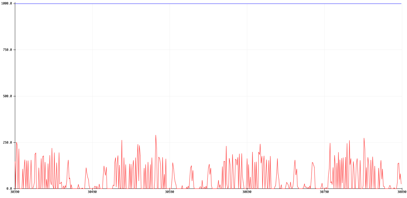
Last time I showed that high frequency switching on a transmitter could be received as "spikes" of voltage on the receiver side.
Dense, thin groups of spikes are digital 1s, thick spikes of noise are the 60Hz leaking in to our 0 signal
It turns out I was wrong; the spikes are only visible because the grounds were galvanically linked. I had done the separation of receiver and transmitter using a USB isolator, which produces its own ground from the laptop's USB power. This ground happens to be produced at the same potential as the transmitter's ground, so they still share the reference.
When I powered the transmitter with a battery pack, the spikes dropped down to the level of the noise. They were still visible to the eye as higher movement bits of noise, but definitely impossible to detect computationally. Time to try something else.
How it works
I'm using a high frequency carrier wave to carry the bits, and an amp to detect the signal in the specific frequency band of the carrier wave. This is basically how radios work. The transmitter uses the digitally-modulated clock signal of the Arduino(8 MHz) to send 0s and 1s. The receiver is a passive RC high-pass filter, followed by an amplifier stage before the ADC.
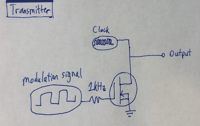
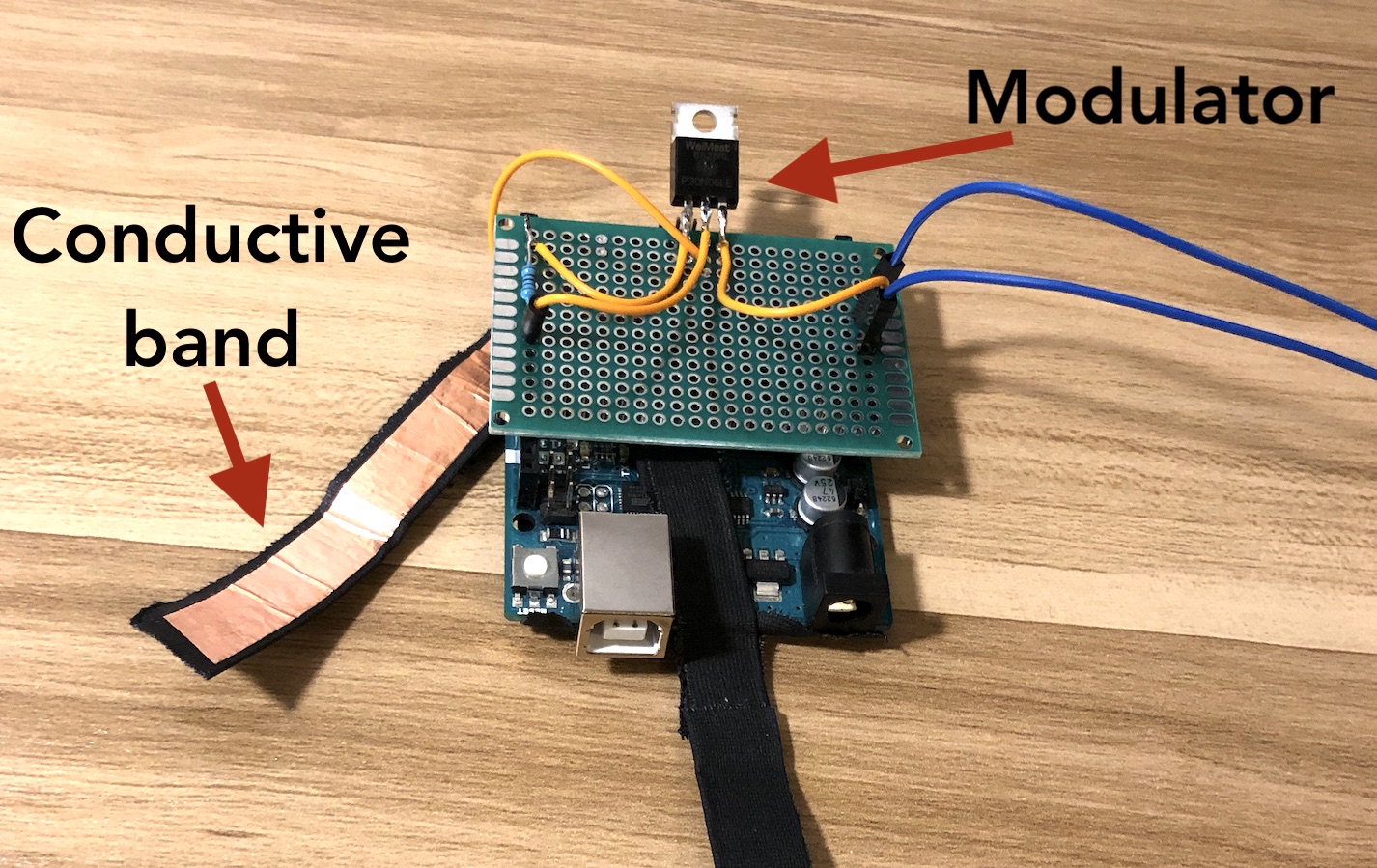
Transmitter
Picture of the transmitter
I was lazy with the earlier prototype and tried to transmit bits using the output from flipping a pin in the loop() of the Arduino as fast as possible. This technique caps out at a frequency of around 100kHz, but I wanted to go higher.
I found a way to output the Arduino's clock signal (16MHz square wave) on a pin. Connecting that to the input of a transistor, I could then turn the clock signal on and off using another pin on the base/gate. This became the transmitter signal: high frequency clock when on, grounded when off.
Raw signal from the transmitter
This turned out to be even easier to implement than what I tried in Pt. 2, since I only had to turn on and off a digital pin in the middle loop.
Circuit for the transmitter, which is just a modulated clock signal
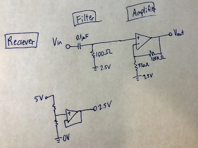
Receiver
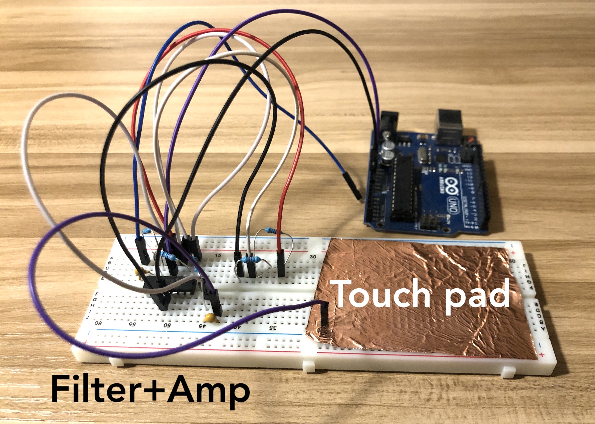
Picture of the receiver
 The receiver side swamps with 60Hz when I touch the input pin. This is both because the human body is a big antenna for all EMI pickup, and because the Arduino's ADC draws current from the source to measure voltages.
To get rid of the 60Hz noise, we built an RC high-pass filter at 159Hz. It works surprisingly well for how close the cutoff frequency is to the noise frequency. After that, we had to add a lot of gain (300x) on the signal to see the square wave being modulated. We also built an artificial ground at 2.5V to act as the central reference for the op amp.
Circuit for the reciever, composed of the stages in the above paragraph
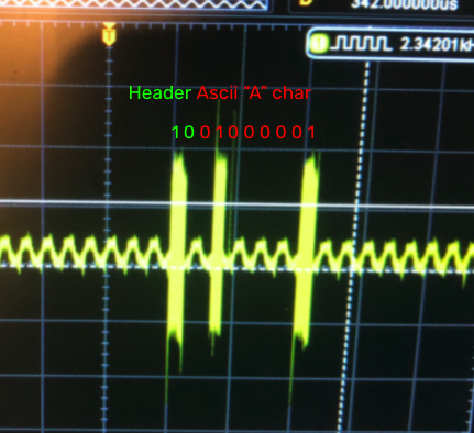
Transmitted signal
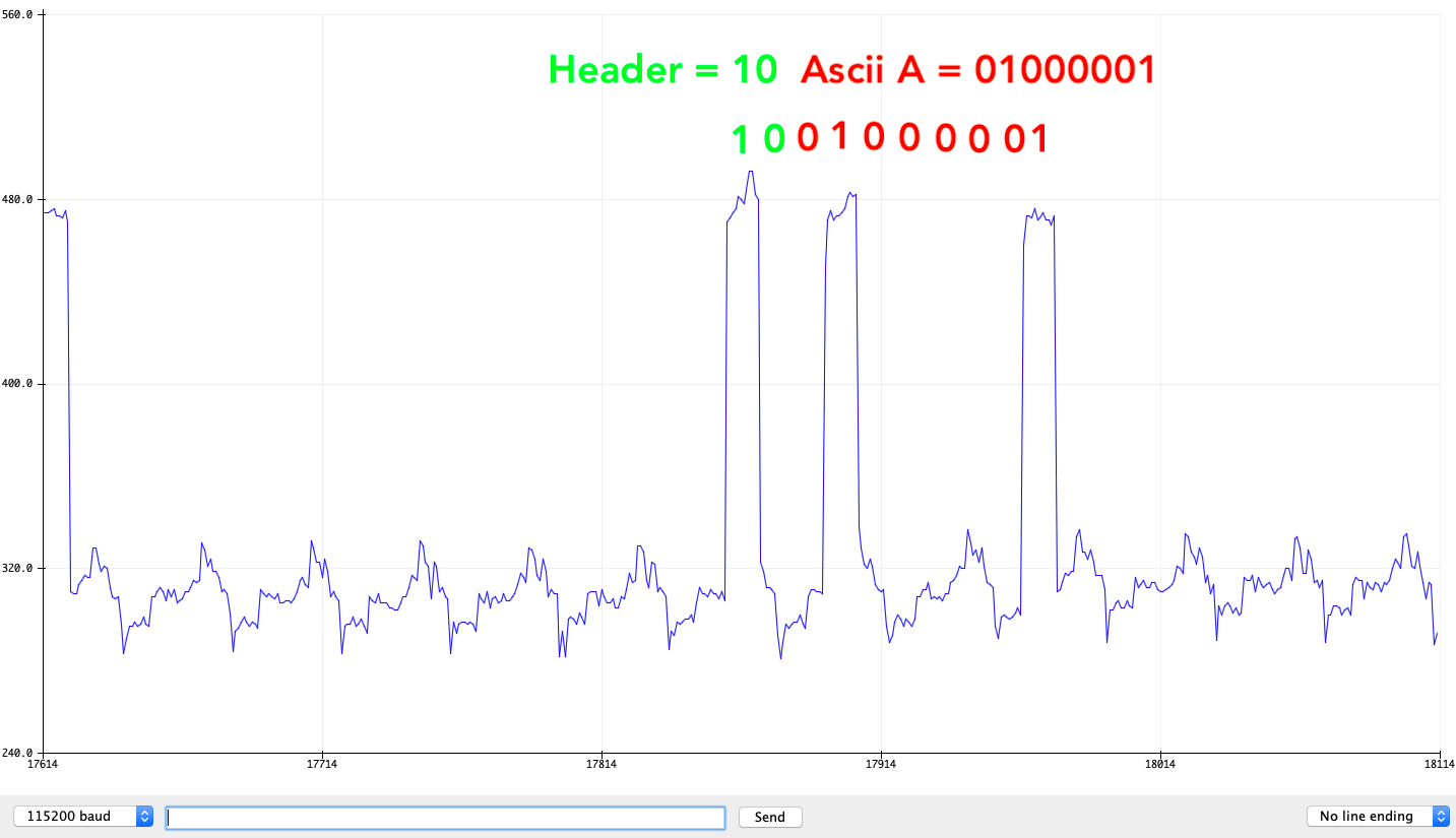
Here's what we're sending. A header of 10 so the reciever knows a signal's coming, then an ASCII character.
Raw output from the transmitter with labeled sections of the data
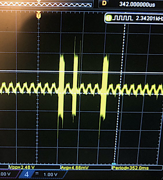
And on the receiving side, the signal appears perfectly among all the 60Hz noise.
Input on the receiving side, after filtering and gain. The bits are clearly visible
Code
The repo can be found here. The transmitter code is very simple, just a digital write and some array reading. The receiver is a little more complex, and a bit hacky to read bitstrings. Works surprisingly well though.
Final Demo
Here's a video of the calendar demo. I didn't have time to rig up two "watches" with different IDs, but my friend who is uninstrumented is unable to access a calendar like I am. Sorry buddy, should've been a technlogist!
Final Notes
Limited signal propagation
The signal does not spread across my entire body, which was a little weird. Wearing the watch on my left wrist, I can trigger the calendar using my left hand, left elbow, nose, and right elbow, but not my right hand. I think with more gain on my receiving side I'd be able to detect it there too. I think this paper talks more about distance of effect.
Low bitrate
The Arduino ADC is fast enough to detect bits reliably at 1kHz, but not much higher than that. I'd need a dedicated ADC and some ring-buffer in software to get a higher bitrate. But honestly, I can't imagine the someone's ID being longer than a kilobyte or so, even if encrypted. that's a lot of bits!
Cool factor
It's dope that the hardware is so simple. One microcontroller, an op amp, and some passives, and your devices can detect not only touch but also WHO touched it. Very powerful, and quite simple to add to a smartwatch *hint hint wink wink*.
If you have questions about implementing this yourself, reach out via email or Twitter. BCC has some dope applications, and I'd love to create more demos using it.